Electrostatic attraction fluid ejecting method and apparatus

a technology of electrostatic attraction and ejecting apparatus, which is applied in the direction of instruments, printing, data recording, etc., can solve the problems of low positioning accuracy of droplets, droplets may not be able to reach, etc., and achieve the freedom of use of electrostatic attraction fluid ejecting apparatus, and high accuracy of drawing operation.

Inactive Publication Date: 2007-08-23
NAT INST OF ADVANCED IND SCI & TECH
View PDF11 Cites 39 Cited by
  • Summary
  • Abstract
  • Description
  • Claims
  • Application Information

AI Technical Summary

Benefits of technology

[0074] With this, it is possible to easily remove the clogging of the nozzle and easily carry out a preliminary ejection of the fluid from the nozzle. In addition, it is possible to appropriately catch the ejected substance from the nozzle by the conductive portion of the catching means.
[0103] According to the above, before carrying out the regular ejection operation, that is, before carrying out the drawing operation, the fluid is ejected from the nozzle and is caught by the conductive portion of the catching means, that is, the preliminary operation is carried out. Thus, by carrying out the preliminary operation in, for example, a predetermined period of time before carrying out the regular ejection operation, it is possible to suppress variations of the amount of ejected fluid in the initial ejection from the nozzle and possible to improve the stability of ejection. Note that the variations of the amount of ejected fluid are caused due to, for example, the increase in the viscosity of the fluid. Moreover, the time period for the preliminary operation may be suitably changed in accordance with, for example, a characteristic of the electrostatic attraction fluid ejecting apparatus.

Problems solved by technology

As a result, the droplet may not be able to reach the printing medium separated by a predetermined distance, or the positioning accuracy of the droplet is low even when the droplet reaches the printing medium.
However, according to the conventional piezo ink jet head and the conventional thermal ink jet head, Problems (A) to (C) below occur when the size of the ejected droplet is decreased, that is, when the ejection energy of the droplet per unit volume is increased.
On this account, it is difficult to improve the ejection energy, per unit volume, of the ejected droplet.
Pressure generated when bubbles are formed is physically limited.
Therefore, it is difficult to improve the ejection energy, per unit volume, of the ejected droplet of the ink.
Therefore, in the case of ejecting extremely fine droplets, it is very difficult to suppress variations in size of the droplets.
Because typical ink contains various solvents, it is difficult to increase the surface tension energy.
Therefore, it is necessary to apply an extremely high voltage of about 2,000 V. On this account, it is difficult to control the driving, and there is a problem in view of the safety of the operation of the ink jet device.
However, the ink flow path becomes narrow in the case of reducing in size the ejection starting portion (nozzle hole).
This causes clogging of the nozzle hole.
Therefore, an ink supply to the ejection starting portion becomes unstable.
Thus, the ejection becomes unstable.
The clogging or unstable ejection is a major factor for fluctuating the size of the dot formed, causing defects, or decreases the image quality.
Moreover, in the case of the method for washing, it is difficult to wash a head since the head has a small ejection diameter.
If the time necessary for this moving back is long, the clogging may occur again, for example, before starting the drawing.
On this account, the drawing can be carried out only with respect to a cylindrical printing medium 302 since the time necessary for this moving back is short in this case, and it is difficult to carry out the drawing with respect to a flat medium since the time necessary for this moving back is long in this case.
Further, the ejection cannot be carried out in the case of using ink made of a substance which dehydrates in a short period of time, such as ink which dehydrates while the printing head 305 is moving.
Moreover, due to, for example, an increase in viscosity of an ejected substance (ink), it is impossible to suppress variations of the amount of ejected ink in an initial ejection.

Method used


Image

  • Electrostatic attraction fluid ejecting method and apparatus
  • Electrostatic attraction fluid ejecting method and apparatus
  • Electrostatic attraction fluid ejecting method and apparatus

Examples


embodiment 1

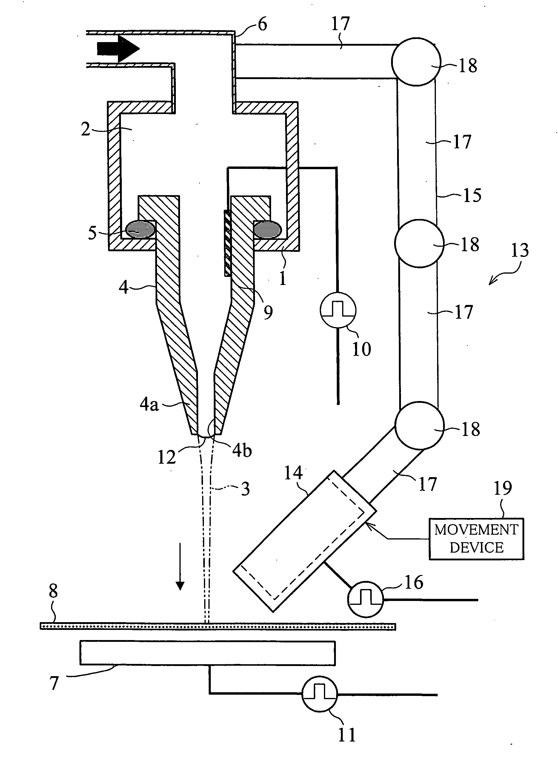
[0165] The following will explain one embodiment of the present invention. Note that the present embodiment will explain an electrostatic attraction ink jet apparatus as an electrostatic attraction fluid ejecting apparatus which uses ink as a fluid.

[0166]FIG. 1 is a diagram showing a schematic configuration of an ink jet apparatus of one embodiment of the present invention. As shown in FIG. 1, the ink jet apparatus includes a nozzle 4 for ejecting ink 2 that is a fluid stored in an ink chamber 1. The nozzle 4 is attached to the ink chamber 1 via a packing 5. With this, an attached portion of the nozzle 4 and the ink chamber 1 is sealed so that the ink 2 in the ink chamber 1 does not leak outwardly from this attached portion.

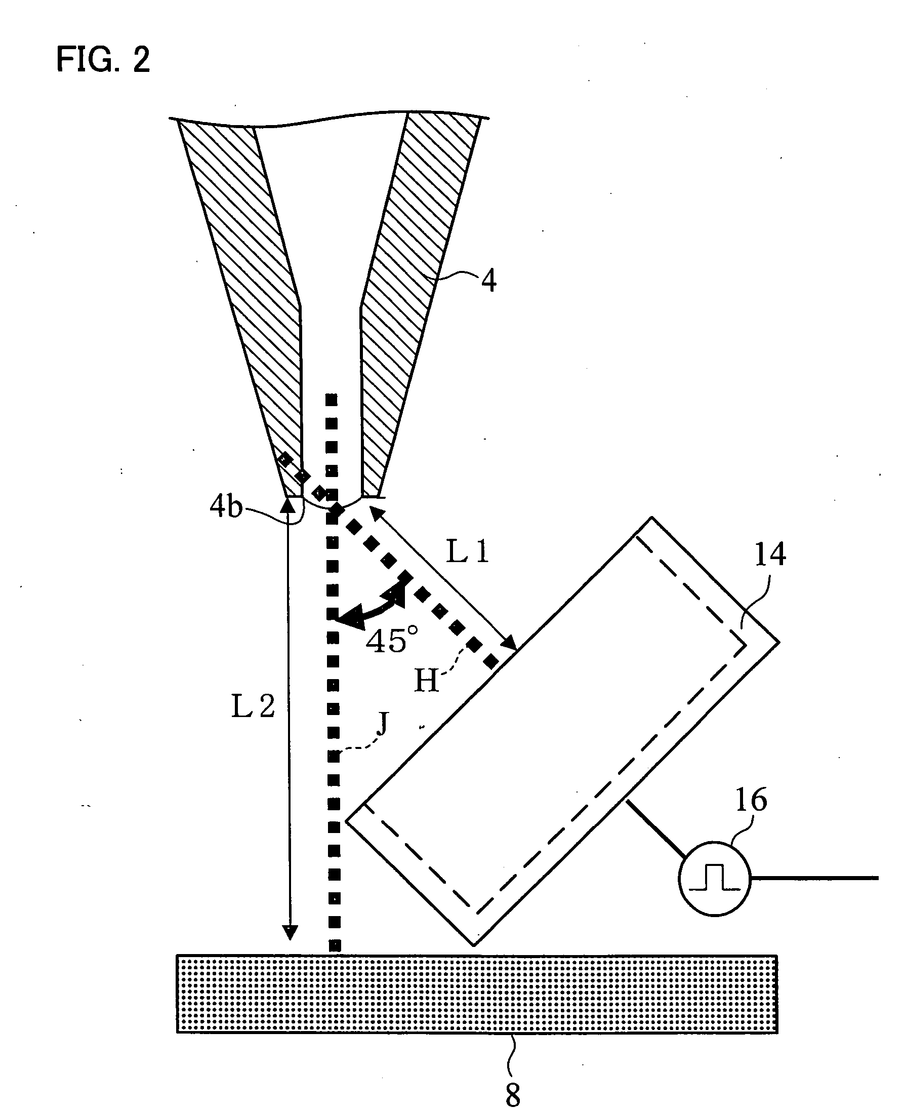
[0167] Moreover, the shape of the nozzle 4 is such that the internal diameter of the nozzle 4 is reduced in size toward the opposite side of the attached portion of the ink chamber 1, that is, toward a top portion 4a that is an ink ejection side. The internal d...

embodiment 2

[0229] The following will explain another embodiment of the present invention in reference to the figures. Note that explanations of the same members as the above embodiment are omitted here.

[0230] Instead of the ink catching portion 14, an ink jet apparatus of the present embodiment includes an ink catching portion 31 shown in FIGS. 6(a) and 6(b). FIG. 6(a) is a plan view of the ink catching portion 31, and FIG. 6(b) is a longitudinal sectional view of the ink catching portion 31.

[0231] The external form and size of the ink catching portion 31 is substantially the same as, for example, those of the ink catching portion 14. The ink catching portion 31 includes, for example, a container portion 32 that is in the form of a cylindrical container, and an attraction electrode portion 33. The attraction electrode portion 33 is connected with the process control portion 16.

[0232] The container portion 32 is made of a low dielectric material, such as organic resin, glass, or silica. The ...

embodiment 3

[0236] The following will explain still another embodiment of the present invention in reference to the figures. Note that explanations of the same members as the above embodiments are omitted here.

[0237] Instead of the ink catching portion 14, an ink jet apparatus of the present embodiment includes an ink catching portion 35 shown in FIGS. 7(a) and 7(b). FIG. 7(a) is a plan view of the ink catching portion 35, and FIG. 7(b) is a longitudinal sectional view of the ink catching portion 35. FIG. 8 is a longitudinal sectional view showing another example of a configuration of the ink catching portion 35.

[0238] The ink catching portion 35 includes the container portion 32 and attraction electrode portion 33 which are similar to those in the ink catching portion 31, and the container portion 32 here includes therein an absorber 36 made of an insulating material. Note that the attraction electrode portion 33 is connected with the process control portion 16.

[0239] The absorber 36 is so ...


PUM


Abstract

An ink jet apparatus electrifies ink (2) in a nozzle (4), and ejects the ink (2) from an ink ejecting hole (4b) onto a printing medium (8) by a first electric field generated between the nozzle (4) and the printing medium (8). The ink jet apparatus includes an ink catching device which includes an ink catching portion (14) provided at a position adjacent to the nozzle (4) and catches an ejected substance ejected from the nozzle (4). In addition, between the nozzle (4) and the ink catching portion (14), the ink jet apparatus applies a voltage for generating a second electric field which (i) causes the ejected substance, which is formed from the ink (2) or the ink (2) whose viscosity is changed, to be ejected from the nozzle (4) and (ii) causes the ink catching portion to attract the ejected substance. With this, in a configuration which utilizes an electrostatic force to eject fluid, it is possible to promptly remove a clogging of an ejection head at any position, and it is also possible to realize less initial ejection fluctuation and improve the reliability of ejection.

Description

TECHNICAL FIELD [0001] The present invention relates to an electrostatic attraction fluid ejecting method and apparatus for ejecting a fluid, such as ink supplied to a nozzle, onto a target by electrostatically attracting the fluid by electrifying the fluid. BACKGROUND ART [0002] Generally, there exist various fluid jet methods by which a fluid, such as ink, is ejected onto a target (printing medium). Here, the following will explain an ink jet printing method in which the ink is used as the fluid. [0003] As drop on demand ink jet printing methods, (i) a piezo printing method in which a piezoelectric phenomenon is utilized, (ii) a thermal printing method in which a film boiling phenomenon of ink is utilized, and (iii) an electrostatic attraction printing method in which an electrostatic phenomenon is utilized, etc are developed. Especially, in recent years, a high-resolution ink jet printing method is strongly demanded. To realize the high-resolution ink jet printing, it is indispen...

Claims


Application Information

Patent Timeline
Patent Type & Authority Applications(United States)
IPC IPC(8): B41J2/41B41J2/06B41J2/18B41J2/095B41J2/165B41J2/185
CPCB41J2/06B41J2/185B41J2/16511B41J2/095
Inventor KAWAI, HIDETSUGUNISHIO, SHIGERUDEGUCHI, HARUHIKOKAKIWAKI, SHIGEAKIMURATA, KAZUHIRO
Owner NAT INST OF ADVANCED IND SCI & TECH
Why Eureka
Try Eureka