Device and method for non-contact scanning of contact lens and contact lens mold geometry

a technology of contact lens and geometry, which is applied in the direction of material analysis using wave/particle radiation, instruments, nuclear engineering, etc., can solve the problems of cylinder and differential shrinkage being difficult to measure and characterize at the moment, the material may undergo non-uniform shrinkage, and the mold material affecting the end produ

Active Publication Date: 2007-08-23
ALCON INC
View PDF16 Cites 54 Cited by
  • Summary
  • Abstract
  • Description
  • Claims
  • Application Information

AI Technical Summary

Benefits of technology

[0012] The present invention also includes an apparatus for measuring the precise geometry of an ophthalmic sample. The ophthalmic sample may be a contact lens, a contact lens mold, an intraocular lens or an optical tool. The apparatus may include a source of electromagnetic radiation at an intensity, a detector to detect the electromagnetic radiation intensity, a fixture for positioning the sample such that the electromagnetic radiation generated by the source passes through the sample and to the detector, a detecting means for detecting the electromagnetic radiation intensity after passing through the sample, and a processing means for processing the electromagnetic radiation intensity detected to obtain a 2-dimensional image of the sample.
[0013] In a further embodiment, the fixture for positioning the sample includes a rotatable platform capable of rotating the sample to a plurality of orientations. The detecting means being capable of detecting the electromagnetic radiation intensity for each orientation of the sample, and the processing means processing the electromagnetic radiation intensity detected for each orientation to obtain a 3-dimensional model of the sample surfaces. The model then representing the precise 3-dimensinoal geometry of the sample surfaces.
[0014] In a further embodiment, the processing means includes a means for applying a sub-pixel edge detection algorithm to the electromagnetic radiation intensity. In another embodiment, the rotatable platform includes more than one rotational stage. In another related embodiment, the rotatable platform includes a first rotational stage axis and an orthogonal second rotational stage axis. In another related embodiment, the rotatable platform may be a Stewart platform, or a parallel kinematics motion stage.
[0015] In further embodiments, the electromagnetic radiation source is capable of producing electromagnetic radiation in the range of 1 micrometer to 0.1 nanometer. The apparatus processing means may include a personal computer. In a related embodiment, the processing means may include a database for archiving the precise geometry of the sample surfaces.

Problems solved by technology

Additionally, the mold material affects the end product, as the mold material may undergo non-uniform shrinkage as the mold is cured.
Defects such cylinder and differential shrinkage are difficult to measure and characterize currently.
The cured lens will not reflect the precise geometry of the mold due to volumetric shrinkage of the lens material.
The determination of the mold and lens geometries presents many challenges.
The optical tool can distort the lens and result in an inaccurate measurement of the true lens geometry.
Of particular difficulty is the measurement of the base curve of the lens.
These techniques are difficult, slow, often inaccurate, and lack desired functionality.
The lens or mold sample must be precisely positioned within the scanner or the accuracy of the measured geometry will be adversely affected.
Most commercially available scanner technologies cannot capture a large area, such as the entire 14 mm diameter of a lens, and are only able to inspect a portion of the sample geometry at a time.
The vision systems and lasers must have a direct line of sight with the surface being measured, which is not always possible on the arcuate surfaces of the contacts lenses, lens molds, and optical tooling.
Because of the direct line of sight or access requirement, the current techniques cannot inspect an object within an object, such as a lens clamped within a mold assembly.

Method used


Image

  • Device and method for non-contact scanning of contact lens and contact lens mold geometry
  • Device and method for non-contact scanning of contact lens and contact lens mold geometry
  • Device and method for non-contact scanning of contact lens and contact lens mold geometry

Examples


Embodiment Construction

[0024] Reference now will be made in detail to the embodiments of the invention. It will be apparent to those skilled in the art that various modifications and variations can be made in the present invention without departing from the scope or spirit of the invention. For instance, features illustrated or described as part of one embodiment, can be used on another embodiment to yield a still further embodiment. Thus, it is intended that the present invention cover such modifications and variations as come within the scope of the appended claims and their equivalents. Other objects, features and aspects of the present invention are disclosed in or are obvious from the following detailed description. It is to be understood by one of ordinary skill in the art that the present discussion is a description of exemplary embodiments only, and is not intended as limiting the broader aspects of the present invention.

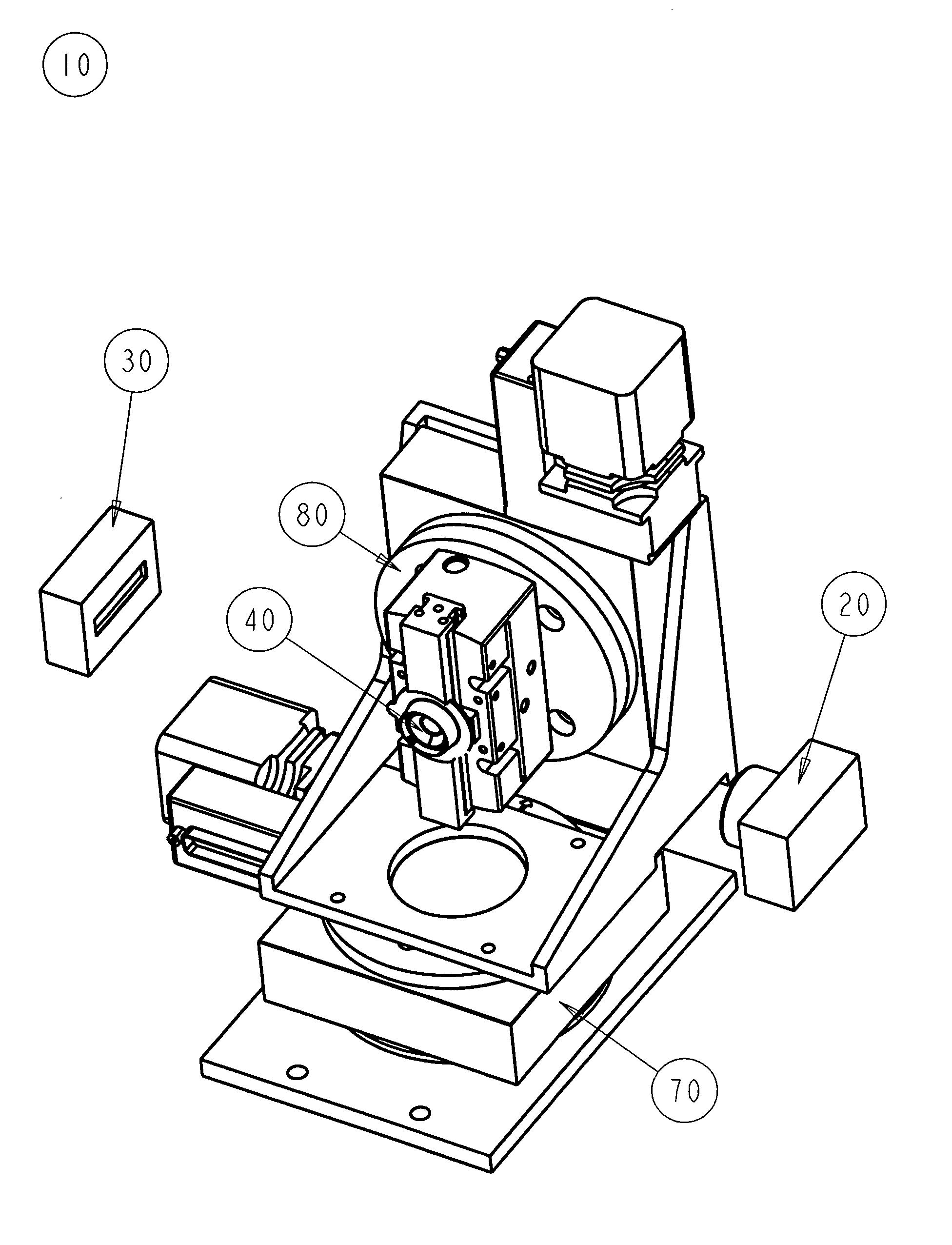
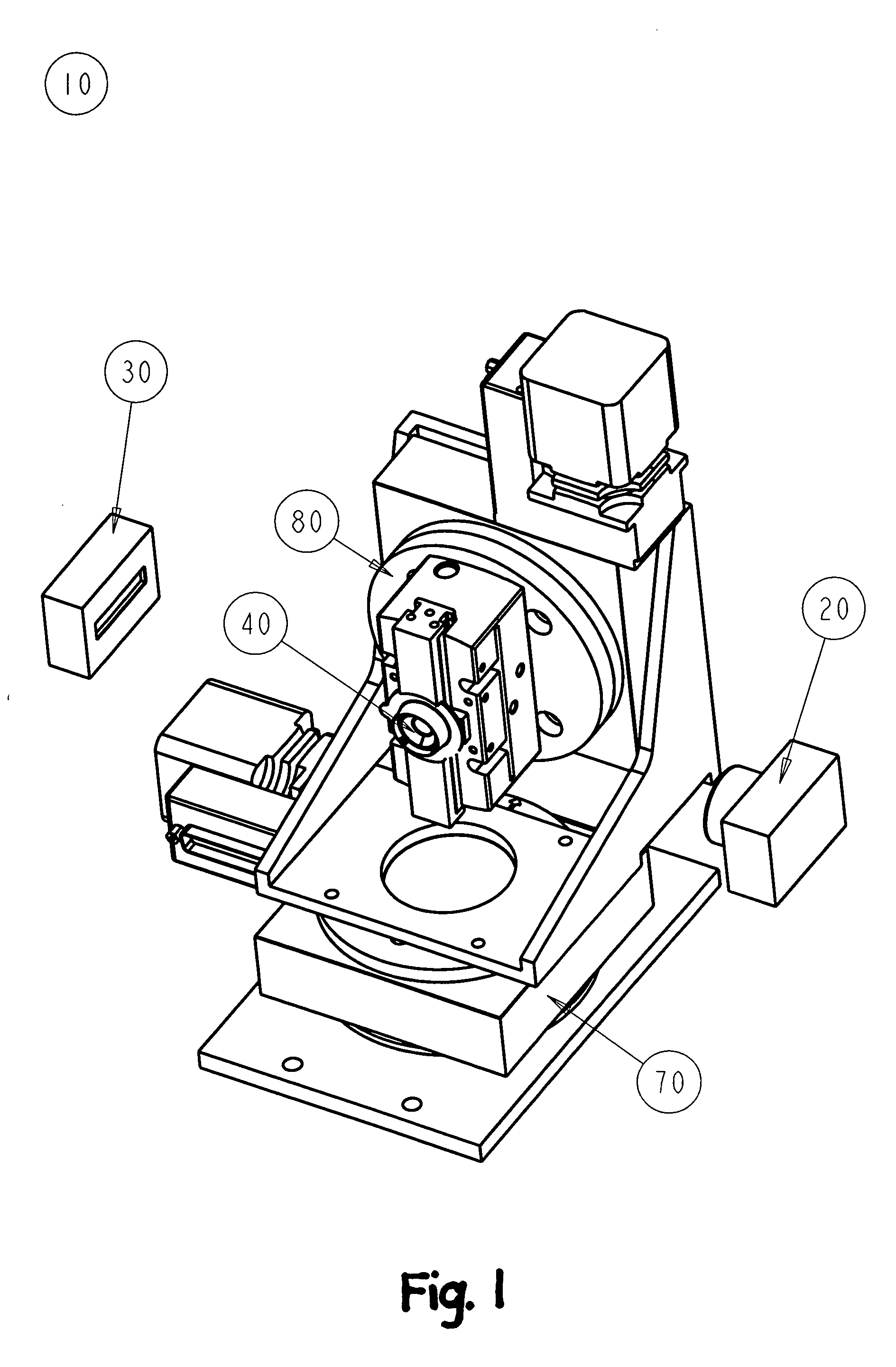
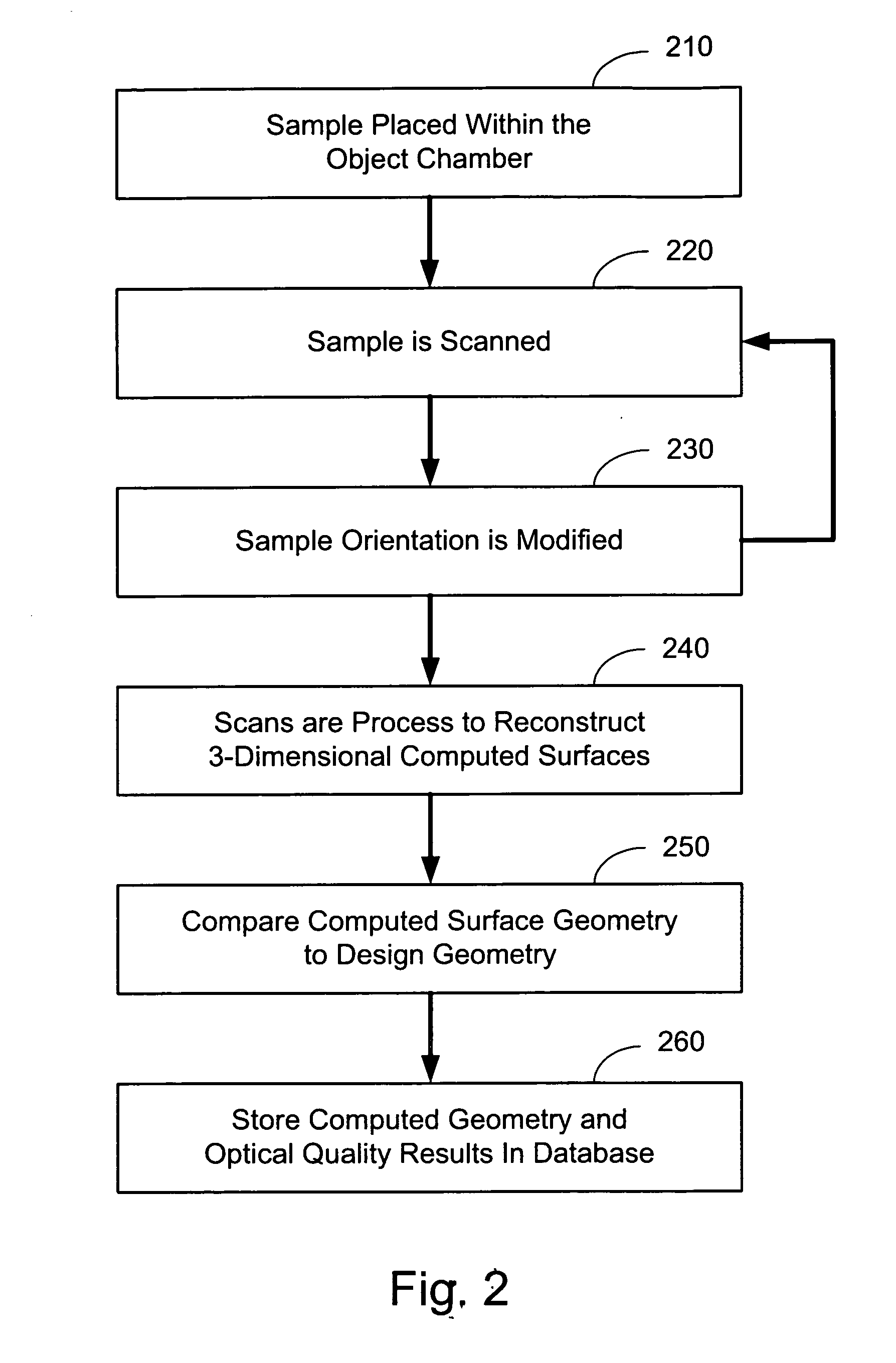
[0025] The present invention comprises an apparatus and method to more accur...


PUM


Abstract

The invention relates to an apparatus and method for non-contact/non-destructive measurement of the geometry of molded ophthalmic lenses and the precision molds and tooling used in the manufacture of the ophthalmic lenses. In particular the present system uses micro computed tomography to measure the geometries.

Description

FIELD OF THE INVENTION [0001] This invention relates to an apparatus and method for non-contact / non-destructive measurement of the geometry of molded ophthalmic lenses and the precision molds and tooling used in the manufacture of the ophthalmic lenses. In particular the present system uses micro computed tomography to measure the geometries. BACKGROUND OF THE INVENTION [0002] Ophthalmic lenses may be created using a variety of methods, one of which includes molding. In a double sided molding process, the lenses are manufactured between two molds without subsequent machining of the surfaces or edges. Such mold processes are described, for example in U.S. Pat. No. 6,113,817, which is expressly incorporated by reference as if fully set forth herein. As such, the geometry of the lens is determined by the geometry of the mold. Typical molding systems include cast molding, which involves using two mold halves, and spin-casting. These methods may also be combined with other machining tech...

Claims


Application Information

Patent Timeline
Patent Type & Authority Applications(United States)
IPC IPC(8): G01B9/00G01B11/24
CPCG01B15/04A61F2/16B29D11/0098G01N23/00
Inventor MORGAN, COURTNEY FLEMHALL, WILLIAM JORDAN
Owner ALCON INC
Why Eureka
Try Eureka