Adapter lens

a technology of adapter and lens, which is applied in the field of adapter lens, can solve the problems of large size of small camera and lens adapter, unsatisfactory external appearance of lens adapter covering such a wide area, and difficult handling, so as to increase the size of camera and facilitate us

Inactive Publication Date: 2007-08-23
SONY CORP
View PDF3 Cites 27 Cited by
  • Summary
  • Abstract
  • Description
  • Claims
  • Application Information

AI Technical Summary

Benefits of technology

[0008]The present invention has been made in view of such a problem and the present invention desires to provide a lens adapter easy to handle and having aesthetically satisfactory external appearance.
[0010]The adapter lens of the embodiment of the present invention is attached to only the upper corner of the body of the camera. Therefore, the adapter lens attached to the camera does not excessively increase the size of the camera and hence the camera is easy to use.
[0011]The adapter lens not uselessly covering parts of the body of the camera other than the upper corner of the body in which the objective lens is disposed is compact and has an aesthetically satisfactory appearance.

Problems solved by technology

Consequently, the assembly of the small camera and the lens adapter is large and is not easy to handle.
The external appearance of the lens adapter covering such a wide area is aesthetically unsatisfactory.

Method used


Image

  • Adapter lens
  • Adapter lens
  • Adapter lens

Examples


first embodiment

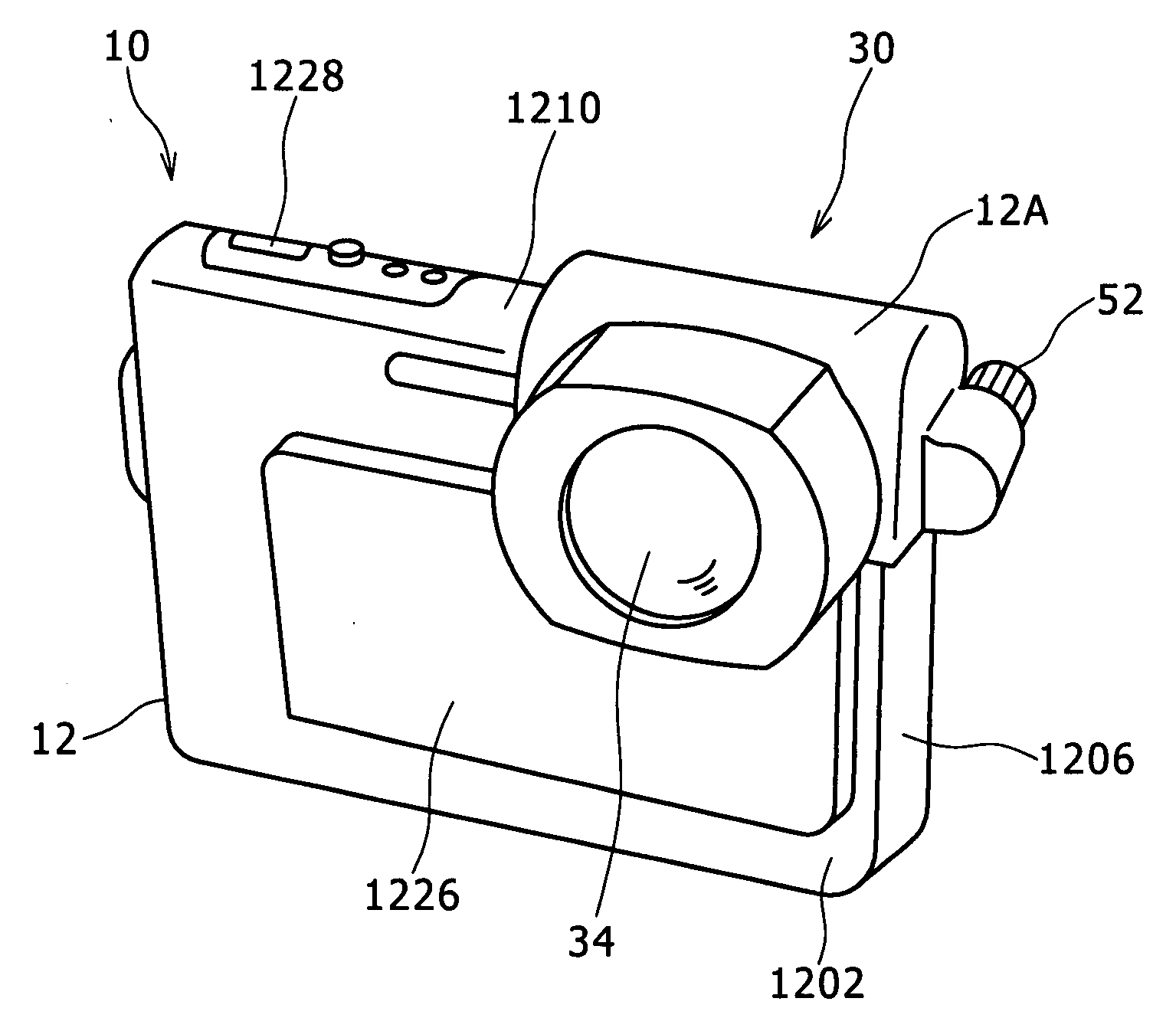
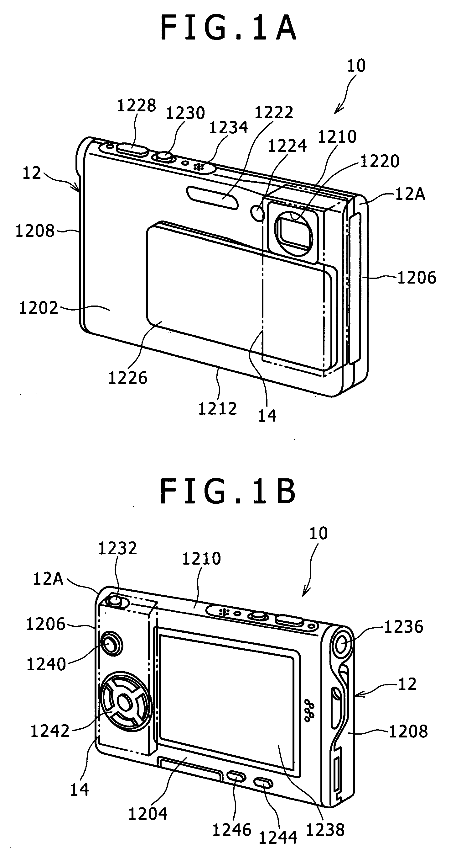
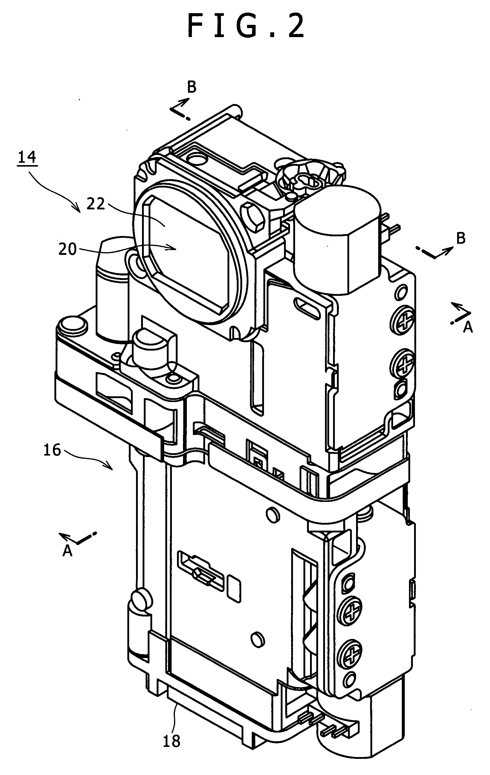
[0039]FIG. 1A is a front perspective view of a camera 10 on which an adapter lens 30 in a first embodiment according to the present invention is mounted, FIG. 1B is a rear perspective view of the camera 10, FIG. 2 is a perspective view of a lens barrel 14 included in the camera 10, FIG. 3 is a sectional view taken on the line A-A in FIG. 2, and FIG. 4 is a sectional view taken on the line B-B in FIG. 2.

[0040]The camera 10 mounted with the adapter lens 30 will be described. In the following description, a side of the camera 10 on the side of an object is the front side, a side of the camera 10 opposite the front side is the rear side, a side on the right side of the camera 10 as viewed from behind the camera 10 is the right side, and a side on the left side of the camera 10 as viewed from behind the camera 10 is the left side.

[0041]Referring to FIGS. 1A and 1B, the camera 10 is a digital still camera having a thin, rectangular body 12 serving as a casing. The body 12 has a small thic...

second embodiment

[0066]An adapter lens 30 in a second embodiment according to the present invention will be described with reference to FIGS. 17 to 20, in which parts like or corresponding to those of the adapter lens 30 in the first embodiment are designated by the same reference characters. FIG. 17 is a perspective view of the adapter lens 30 in the second embodiment, FIG. 18 is a front elevation of the adapter lens 30 mounted on a camera 10, FIG. 19 is a side elevation of the adapter lens 30 mounted on the camera 10, and FIG. 20 is a rear view of the adapter lens 30 mounted on the camera 10.

[0067]The adapter lens 30 in the second embodiment has a side plate 36 having a base part 3602 provided with a boss 3604, and a rear plate 40 having a base part 4002. The boss 3604 is provided with a threaded hole 3614 and has a rear end surface lying on the front side of the rear end of a side plate 36. The rear plate 40 has a base part 4002 provided with a joining part 4004 provided with a through hole 4014....


PUM


Abstract

An adapter lens has a front plate, an optical member, a side plate, an upper plate and a rear plate. The adapter lens can be detachably attached to an upper left-hand corner of a body included in a camera. The adapter lens is mounted on the camera with the front plate, the side plate, the upper plate and the rear plate in contact with a part of the front surface around the objective lens, an upper part of the side surface near the corner of the body, a part of the upper surface near the corner of the body, and an upper part of the rear surface near the corner of the body, respectively. A screw is passed through a through hole formed in connecting part of the rear plate and screwed into a threaded hole formed in a boss formed integrally with the side plate to hold the body between the front plate and the rear plate.

Description

CROSS REFERENCES TO RELATED APPLICATIONS[0001]The present invention contains subject matter related to Japanese Patent Application JP 2006-042846 filed in the Japanese Patent Office on Feb. 20, 2006, the entire contents of which being incorporated herein by reference.BACKGROUND OF THE INVENTION[0002]The present invention relates to an adapter lens.[0003]Some camera, such as a digital still camera, is designed to change the magnification of its objective lens for wide-angle photography or telephotography by screwing a conversion lens into an internally threaded end part of the lens barrel of the objective lens.[0004]Small cameras having a thin, rectangular body have been provided in recent years. The lens barrel of such a small camera does not have an internally threaded end part and hence an adapter lens, such as a conversion lens, cannot be attached to the lens barrel.[0005]A lens adapter proposed in JP-A 2004-264367 has an adapter attached to the body of the camera, and a cylindri...

Claims


Application Information

Patent Timeline
Patent Type & Authority Applications(United States)
IPC IPC(8): G03B17/00
CPCG03B17/02
Inventor KUBO, TAKASHI
Owner SONY CORP
Why Eureka
Try Eureka