Receiver apparatus, receiving method, and wireless communication system
a receiving method and receiver technology, applied in the field of receiving apparatus and receiving method, can solve the problems of degrading the receiving quality, affecting and dominating the multipath interference rather than the improvement obtained by the rake reception method, so as to improve the quality of the receiving signal in the multipath fading environment, reduce the multipath interference of the signal, and ensure the transmission accuracy
- Summary
- Abstract
- Description
- Claims
- Application Information
AI Technical Summary
Benefits of technology
Problems solved by technology
Method used
Image
Examples
first embodiment
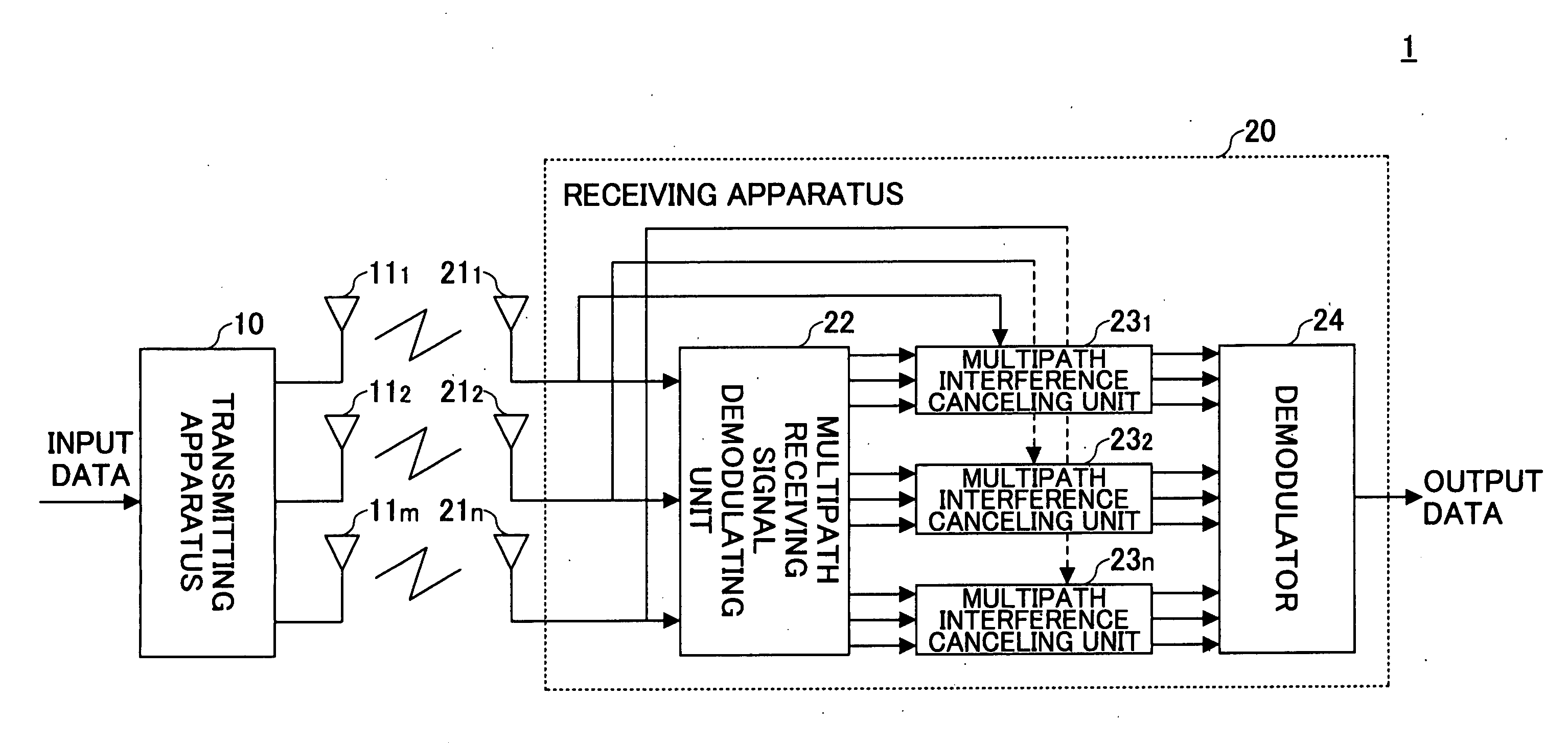
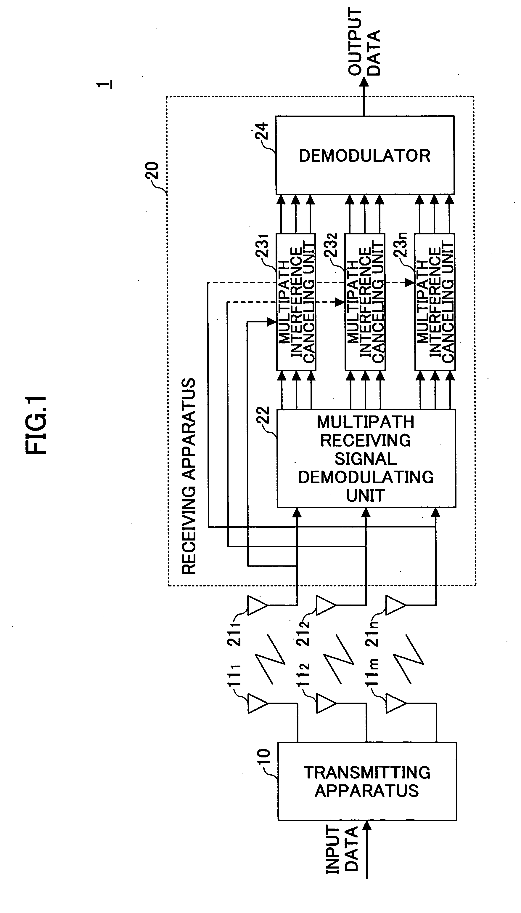
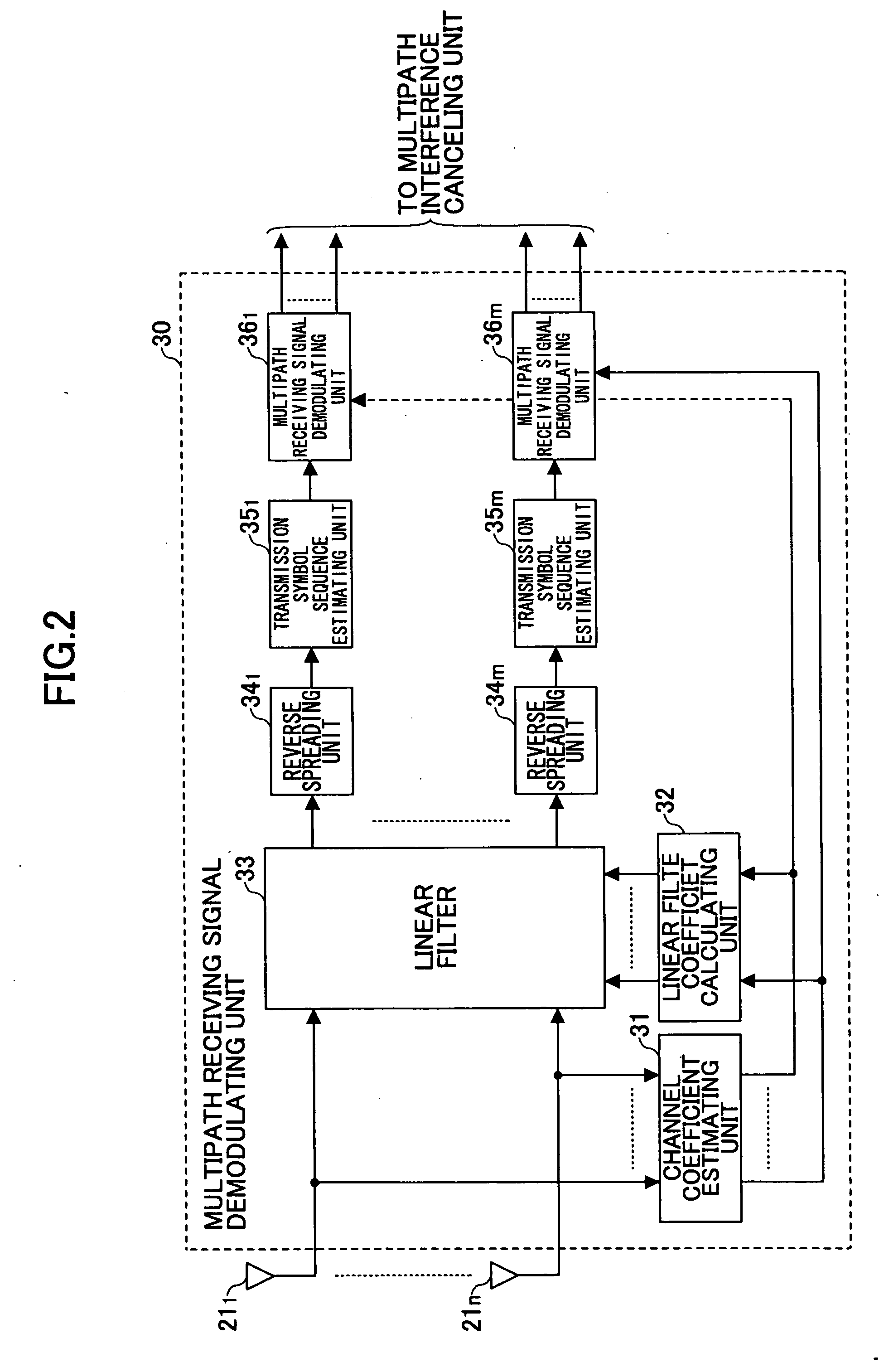
[0107] According to the multipath receiving signal demodulator 30 of the first embodiment, signals rn(t) received by N receiving antennas 211 through 21n are provided to the channel coefficient estimating unit 31, and channel coefficients hm,n,l of paths between the receiving antennas 211 through 21n and the transmitting antennas 111 through 11n (FIG. 1) are estimated.
[0108] Then, the linear filter coefficient calculating unit 32 calculates a coefficient for the linear filter 33, which carries out a filtering process for equalization using the linear filter coefficient. The process described above can be realized by signal processing in one of the time domain and the frequency domain; in the following, descriptions are presented about an example wherein signal processing is carried out in the frequency domain.
[0109] The linear filter coefficient calculating unit 32 calculates the linear filter coefficient that simultaneously minimizes delay path components of signals from a desired...
second embodiment
[0141] According to the multipath receiving signal demodulator 40 of the second embodiment, signals rn(t) received by the receiving antennas 211 through 21n are provided to the channel coefficient estimating unit 41, and the channel coefficients hm,n,l of the paths between the receiving antennas 211 through 21n and the transmitting antennas 111 through 11n are estimated.
[0142] Next, the reverse spreading units 42 through 45, which number N×L, perform reverse spreading of the received signals rn(t) with the same spreading signal as the spreading signal used at the time of transmission at the receiving timing of each path, and N×L reverse-spread signals Zn,l for the paths of the receiving antennas are obtained.
[0143] The transmission symbol candidate generating unit 46 generates and outputs transmission symbols dm,i corresponding to each transmitting antenna, where “i” is a symbol candidate number that suffices for Expression 32.
(1≦i≦C) [Expression 32]
[0144] where C is the number o...
third embodiment
[0163] According to the multipath receiving signal demodulator 50 of the third embodiment, the channel coefficient estimating unit 51 receives the signals rn(t) received by the receiving antennas 211 through 21n, and the channel coefficients hm,n,l of the paths between the receiving antennas 211 through 21n and the transmitting antennas 111 through 11n are estimated.
[0164] Next, the reverse spreading units 52 through 55, which number N×L, perform reverse spreading of the received signals rn(t) with the same spreading signal as used at the time of transmission at the receiving timing of each path, and N×L reverse-spread signals zn,l of the paths of the receiving antennas are obtained.
[0165] Next, the QR factorizing unit 56 generates a channel matrix as shown by Expression 50, the channel matrix including channel coefficients expressed in N×L rows×M columns, performs QR factorization of the channel matrix, and a Q matrix and an R matrix are output. Channel Matrix H=[h1,1,1h2,1,1...
PUM
 Abstract
Description
Claims
Application Information
 - R&D
- Intellectual Property
- Life Sciences
- Materials
- Tech Scout
- Unparalleled Data Quality
- Higher Quality Content
- 60% Fewer Hallucinations
Browse by: Latest US Patents, China's latest patents, Technical Efficacy Thesaurus, Application Domain, Technology Topic, Popular Technical Reports.
© 2025 PatSnap. All rights reserved.Legal|Privacy policy|Modern Slavery Act Transparency Statement|Sitemap|About US| Contact US: help@patsnap.com


