Method and apparatus for reducing multi-path interference in dispersion compensation systems

a multi-path interference and compensation system technology, applied in the field of optical communication, can solve problems such as chromatic dispersion degradation due to chromatic dispersion in optical transmission medium, affecting the performance affecting the quality of optical transmission medium, so as to reduce multi-path interference

Inactive Publication Date: 2005-03-08
II VI DELAWARE INC
View PDF6 Cites 0 Cited by
  • Summary
  • Abstract
  • Description
  • Claims
  • Application Information

AI Technical Summary

Benefits of technology

In accordance with another exemplary embodiment of the present invention, a method of reducing multi-path interference comprises pumping a dispersion compensating optical waveguide with light to provide suitable selective gain to a fundamental mode of the dispersion compensating optical waveguide so that MPI from said dispersion compensating optical waveguide is significantly reduced.

Problems solved by technology

In optical transmission systems, waveform degradation due to chromatic dispersion in the optical transmission medium can be problematic, particularly as transmission speeds continue to increase.
Moreover, impurities in the waveguide material, mechanical stress and strain, and temperature effects can also affect the index of refraction, further adding to the ill effects of chromatic dispersion.
In digital optical communications, where the optical signal is ideally a square wave, bit spreading due to chromatic dispersion can be particularly problematic.
When the overflow becomes excessive, intersymbol interference (ISI) may result.
ISI may result in an increase in the bit-error rate to unacceptable levels.
These additional modes can result in multi-path interference (MPI), a well-known system impairment.
If light is launched from a single laser source into a fiber, and subsequently divides among these plurality of paths, the light in each separate path will accumulate a certain amount of relative phase delay.
If the light from these paths recombines in total or in part, coherently or incoherently, interference can result.
This begets intensity variations, and ultimately results in system impairment.
However, as described above, the need for increasingly accurate dispersion compensation often necessitates the design of waveguides that unfortunately allow the propagation of multiple modes.

Method used


Image

  • Method and apparatus for reducing multi-path interference in dispersion compensation systems
  • Method and apparatus for reducing multi-path interference in dispersion compensation systems

Examples


Embodiment Construction

In the following detailed description, for purposes of explanation and not limitation, exemplary embodiments disclosing specific details are set forth in order to provide a thorough understanding of the present invention. However, it will be apparent to one having ordinary skill in the art having had the benefit of the present disclosure, that the present invention may be practiced in other embodiments that depart from the specific details disclosed herein. Moreover, descriptions of well-known devices, methods and materials may be omitted so as to not obscure the description of the present invention.

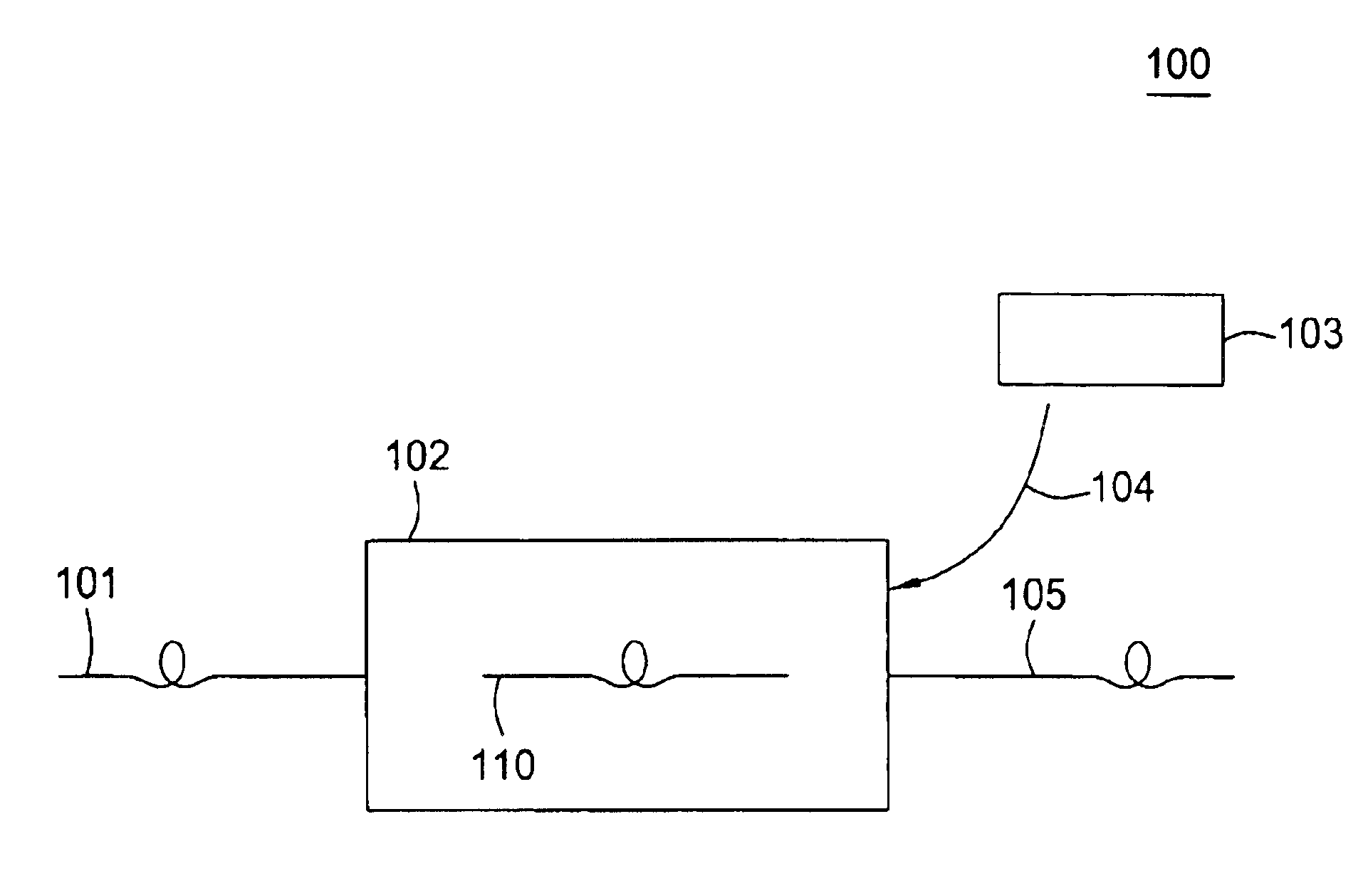
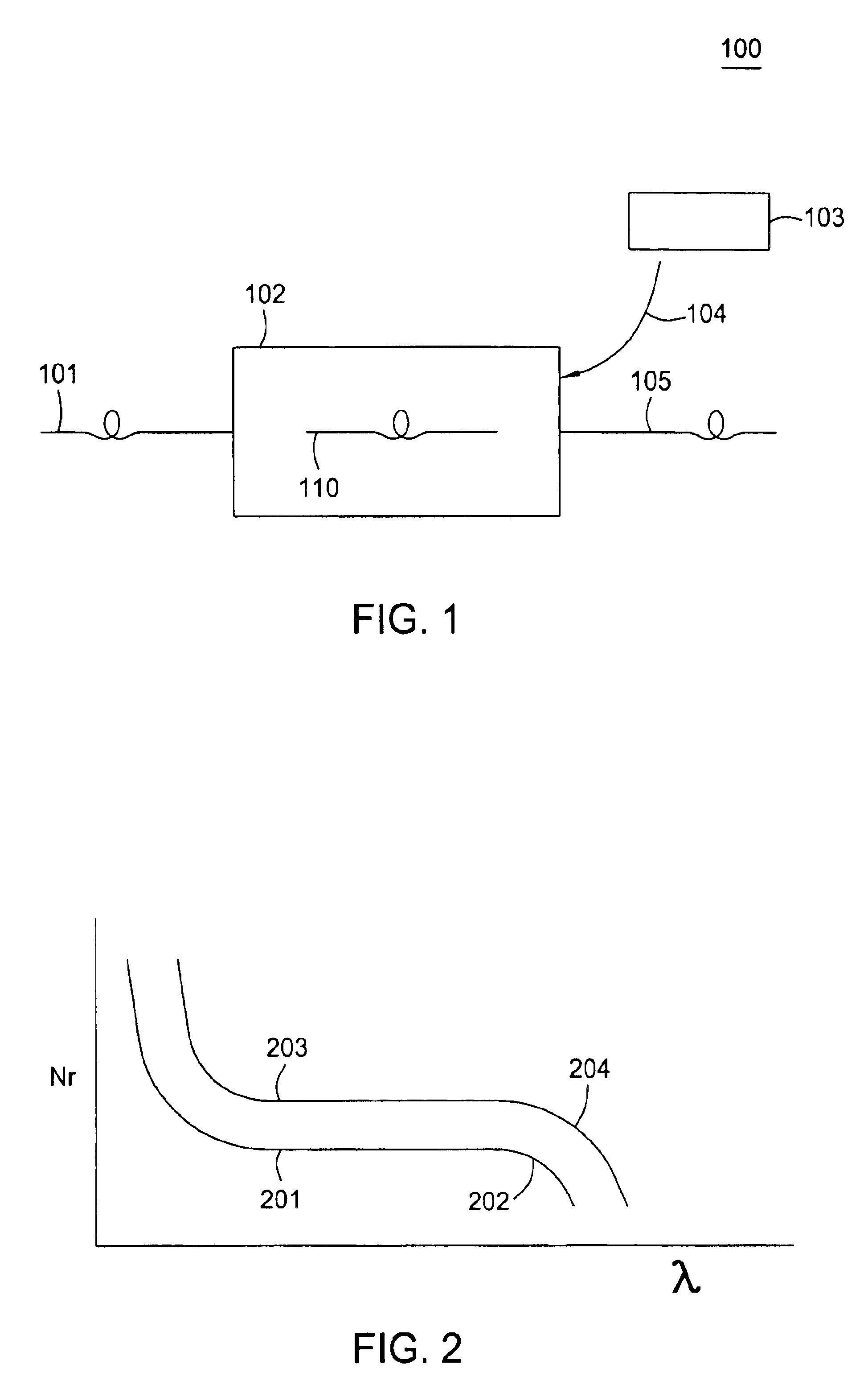
Briefly, in accordance with exemplary embodiments of the present invention described in detail herein, an optical apparatus and method reduces MPI in dispersion compensating (DC) optical waveguides used in a variety of optical links by pumping the DC waveguides with light. Usefully, this enables DC waveguides to be designed to provide a greater degree of dispersion compensation, or dispe...


PUM

PropertyMeasurementUnit
wavelengthaaaaaaaaaa
lengthaaaaaaaaaa

Abstract

An optical apparatus comprises a dispersion compensating optical waveguide, and an optical pump that pumps the dispersion compensating optical waveguide with light. The light from the pump provides suitable selective gain to a fundamental mode of the dispersion compensating optical waveguide that multi-path interference is substantially reduced.A method of reducing multi-path interference comprises pumping a dispersion compensating optical waveguide with light to provide suitable selective gain to a fundamental mode of the dispersion compensating optical waveguide so that MPI from said dispersion compensating optical waveguide is significantly reduced.

Description

FIELD OF THE INVENTIONThe present invention relates generally to optical communications, and specifically to a method and apparatus for reducing multi-path interference (MPI) in optical links.BACKGROUNDOptical transmission systems, including optical fiber communication systems, have become an attractive alternative for carrying voice and data at high speeds. In optical transmission systems, waveform degradation due to chromatic dispersion in the optical transmission medium can be problematic, particularly as transmission speeds continue to increase.Chromatic dispersion results from the fact that in transmission media such as glass optical waveguides, the higher the frequency of the optical signal, the greater the refractive index. The refractive index in a bulk material at a particular frequency is defined to be the ratio of the vacuum wavelength of the signal at that frequency to the wavelength of the signal in the material. Equivalently, it is defined to be the ratio of the phase ...

Claims


Application Information

Patent Timeline
Patent Type & Authority Patents(United States)
IPC IPC(8): H04B10/18
CPCG02B6/02261H04B10/2537G02B6/0228G02B6/03633
Inventor MOZDY, ERIC J.WOOD, WILLIAM A.
Owner II VI DELAWARE INC
Why Eureka
Try Eureka