Wearable equipment and positioning antenna thereof

A positioning antenna and ring-shaped technology, applied in the field of electronic communication, can solve the problems of low positioning accuracy of wearable devices, achieve the effects of reducing multipath interference, good reception, and improving positioning accuracy

Pending Publication Date: 2020-08-04
GUANGDONG XIAOTIANCAI TECH CO LTD
View PDF0 Cites 1 Cited by
  • Summary
  • Abstract
  • Description
  • Claims
  • Application Information

AI Technical Summary

Problems solved by technology

[0004] The purpose of the present invention is to provide a wearable device and its positioning antenna, aiming to solve the technical problem of low positioning accuracy of existing wearable devices

Method used


Image

  • Wearable equipment and positioning antenna thereof
  • Wearable equipment and positioning antenna thereof
  • Wearable equipment and positioning antenna thereof

Examples


Embodiment 1

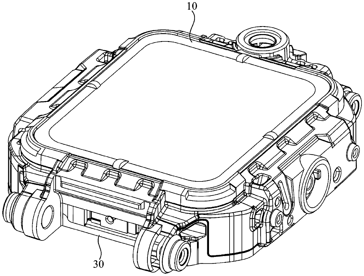
[0037] Please combine Figure 1 to Figure 3 As shown, a wearable device includes a positioning antenna 10 and a circuit board 20 with a radio frequency port and a ground port. The wearable device receives navigation satellite signals through the positioning antenna 10 .

[0038] Specifically, combine figure 1 As shown, the wearable device further includes a housing 30 , and the circuit board 20 and the positioning antenna 10 are both disposed in the housing 30 .

[0039] The above-mentioned positioning antenna 10 will be described in detail below with reference to the accompanying drawings.

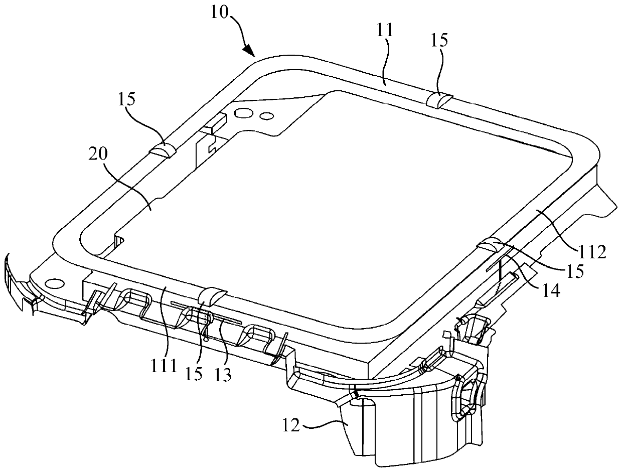
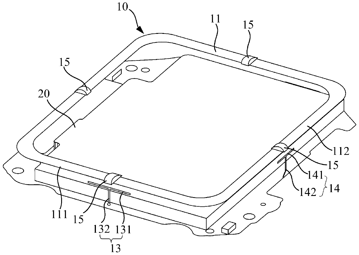
[0040] Please combine Figure 1 to Figure 3 As shown, a positioning antenna 10 includes a ring-shaped radiator 11, a coupling body 12, a feeding branch 13 and a grounding branch 14 respectively coupled to the ring-shaped radiator 11, and the ring-shaped radiator 11 is coupled with a coupling body 12. The coupling body 12 extends along the edge of the annular radiator 11, the end of the...

Embodiment 2

[0059] The difference between the present embodiment and the first embodiment is that the feeding branch 13 includes a feeding arm and a capacitor, and the capacitor is arranged at an end of the feeding arm close to the annular radiator 11 . Wherein, one end of the feeding arm away from the capacitor is connected to the radio frequency port of the circuit board 20 , and the other end of the feeding arm is connected to the annular radiator 11 through the capacitor.

[0060] From Figure 4 It can be seen that the above-mentioned positioning antenna 10 resonates at GPSL1 frequency band -1575 MHz, which indicates that the above-mentioned positioning antenna 10 effectively realizes right-handed circularly polarized radiation and is good at receiving navigation satellite signals.

[0061] From Figure 5 and Figure 6 It can be seen that when the above-mentioned positioning antenna 10 works in the GPS L1 frequency band-1575MHz, the axial ratio of the top (phi=0°, theta=0°) of the p...


PUM


Abstract

The invention relates to the technical field of electronic communication, and provides a positioning antenna and wearable equipment. The positioning antenna comprises an annular radiator which is connected with a coupling body in a coupling manner, and the coupling body extends along the edge of the annular radiator; the positioning antenna further comprises a feed branch knot which is in couplingconnection with the annular radiator; one end, far away from the annular radiator, of the feed branch knot is used for accessing a radio frequency signal; the positioning antenna further comprises agrounding branch knot which is in coupling connection with the annular radiator; one end, far away from the annular radiator, of the grounding branch knot is used for accessing a geoelectric signal; the annular radiator of the positioning antenna can generate right-handed circular polarization radiation, so that the positioning antenna can better receive a navigation satellite signal, and meanwhile, the right-handed circular polarization radiation generated by the annular radiator can also filter the left-handed circular polarization navigation satellite signal reflected by a tall building orthe ground to reduce multipath interference; and the positioning precision of the positioning antenna of the wearable equipment is effectively improved.

Description

technical field [0001] The invention relates to the technical field of electronic communication, and in particular provides a wearable device and a positioning antenna thereof. Background technique [0002] With the continuous development of electronic communication technology, wearable devices are more and more favored by people. [0003] However, the positioning accuracy of wearable devices has been criticized by people. The positioning antennas of traditional wearable devices are mostly linearly polarized antennas, but the signals sent by navigation satellites are right-handed circularly polarized signals after passing through the ionosphere. Therefore, the positioning antennas of wearable devices cannot receive all the signals of navigation satellites; Or, after the navigation satellite signal is reflected oddly by the ground, tall buildings, trees, etc., it will become a left-hand circularly polarized signal, and the resulting multipath interference will further reduce...

Claims


Application Information

Patent Timeline
IPC IPC(8): H01Q1/36H01Q1/50H01Q1/48H01Q7/00H01Q15/24H01Q1/27
CPCH01Q1/273H01Q1/36H01Q1/48H01Q1/50H01Q7/00H01Q15/24
Inventor 梅波江清华
Owner GUANGDONG XIAOTIANCAI TECH CO LTD
Why Eureka
Try Eureka