Method and apparatus for sensing impact between a vehicle and an object

a technology of sensing apparatus and vehicle, applied in the field of sensing impact, can solve the problems of obtaining clear satisfactory indication, limited flexibility of components, unlikely return to working condition, etc., and achieve the effect of reducing possible injury to pedestrians

Inactive Publication Date: 2007-08-23
059312 N B
View PDF11 Cites 27 Cited by
  • Summary
  • Abstract
  • Description
  • Claims
  • Application Information

AI Technical Summary

Benefits of technology

[0006] The present invention is concerned with detecting and classifying impacts which are likely to be less strong and, frequently, may not result in any great danger to the occupants. An object of the present invention is to detect an impact between a pedestrian and a vehicle and actuate a safety device which will reduce possible injury to the pedestrian, while preventing actuation when impacts with other objects such as poles, barriers, and walls are detected.
[0010] In the above prior art, the sensors are designed with loss on one side, providing an asymmetrical loss and bipolar response, so that a sensor zone will respond with an increase in light throughput to a given polarity of bend, and have a decreased throughput for the opposite polarity of bend. The sensor zone on the fiber has a bipolar response, and each portion within the zone also has the bipolar response. Consequently, the overall response of the zone is the integral of curvature over the zone length, which amounts to the net angle from beginning to end of the zone. This is useful in maintaining angular accuracy for sensors that have curvature detail within a zone, but has the unfortunate consequence that inflected bends (bends containing positive and negative components) within the zone may sum to zero.
[0014] In applications requiring response to more than one plane intersecting the axis of the fiber, more thin light-loss strips may be added around the circumference of the fiber. Alternatively, a light-loss strip may wind around the fiber in a helical shape. Impacted shapes also typically involve impacted pressure fields that occur at similar locations to the impact bends. It is possible to either ignore the pressure by designing the attachment of the sensors to exclude pressure effects but respond only to shape (such as by mounting the sensor in a slot within the bumper with free air on one side of the sensor), or to use pressure as the means of classifying shapes and measuring the time progression and mass of intrusion, with or without the combined measurement of bending. In this case the light-loss areas may be created by using the pressure of an impact to press a film with varying surface profile into the fiber at a known location at the time of Impact Suitable films include woven screens, sandpaper, and sinuated or waffle-patterned plastic. The impression film will create microbends in the fiber, which will result in light being lost from the core into the cladding or out of the cladding. Microbends are any series of small bends or sinuations along the length of an intended sensor location. The impression film may be located on the sides of the fiber facing away from and toward the impact, or on one side only. If located on both sides, the effects of light-loss due to pressure and of bending while losing light will be synergistic, and symmetrical to both directions of curvature, so it is preferable to have the impression film on both sides. If the impression film is located on one side only, the effects are synergistic for pressure and bend but will be less symmetrical for both directions of bend. Creation of loss surfaces by this method has the advantage that when the sensor is not being impacted, there is very little light-loss, so that the change upon impact is very large.
[0024] Further, the front end construction may be changed to diminish bends of multiple polarities within a sensing zone. For instance, stiffness may be increased to prevent inflected bends from occurring on a scale where a single sensor would be subjected to both positive and negative bends. Or, a layer of resilient material like foam may be placed between a stiff front bumper and the sensory fibers. This will have the effect of absorbing inflected bends from the earliest portion of the impact when the contact area between an object and the bumper is small compared to a sensor length, and thereafter (after a short delay) transmitting all of the non-inflected bend.
[0025] For any type or configuration of sensor and front end construction, the classification accuracy may be optimized by using combinations of algorithms, testing, and modelling approaches. This invention is aimed at optimizing the locational and time-progression aspects of the signal contents, and minimizing the number of sensors required to make a classification.
[0029] Light-loss zones may preferably be created by abrasion, ablation, or impact, combined with light-absorption. The objective is to create a loss zone with an amount of loss invariant over time, but that varies with bending. Treatment to form the loss zone may vary from low-depth abrasion of the surface, in which case a thoroughly absorptive layer is applied to ensure full loss of scattered light, to high-depth notches, which may not require significant additional absorptive layer to obtain full modulation by bend. However, the light-absorbing layer will always be desirable for reducing the effects of light from other sources external to the fiber, and may include adhesive properties and sealing properties. An example of abrasion is roughening by sandpaper or sand-blasting. An example of ablation is removal of material at low temperature by ultraviolet laser. An example of impact treatment is pressing a sharpened blade into the fiber to create notches.

Problems solved by technology

However there is a problem in obtaining clear satisfactory indication of an impact.
Drawbacks to this method include limited flexibility of the components, unlikely return to a working condition after an impact, and interference from electrical fields and impulses.
PVDF sensors suffer from variability of response, poor integrity of electrical connections when bent, and the requirement for high impedance circuitry with consequent reliability problems in wet environments.
Drawbacks include poor flexibility at low temperatures, material properties which must be tailored for both mechanical flexibility and electrical conduction, and changes in sensitivity to bending at different temperatures.

Method used


Image

  • Method and apparatus for sensing impact between a vehicle and an object
  • Method and apparatus for sensing impact between a vehicle and an object
  • Method and apparatus for sensing impact between a vehicle and an object

Examples


Embodiment Construction

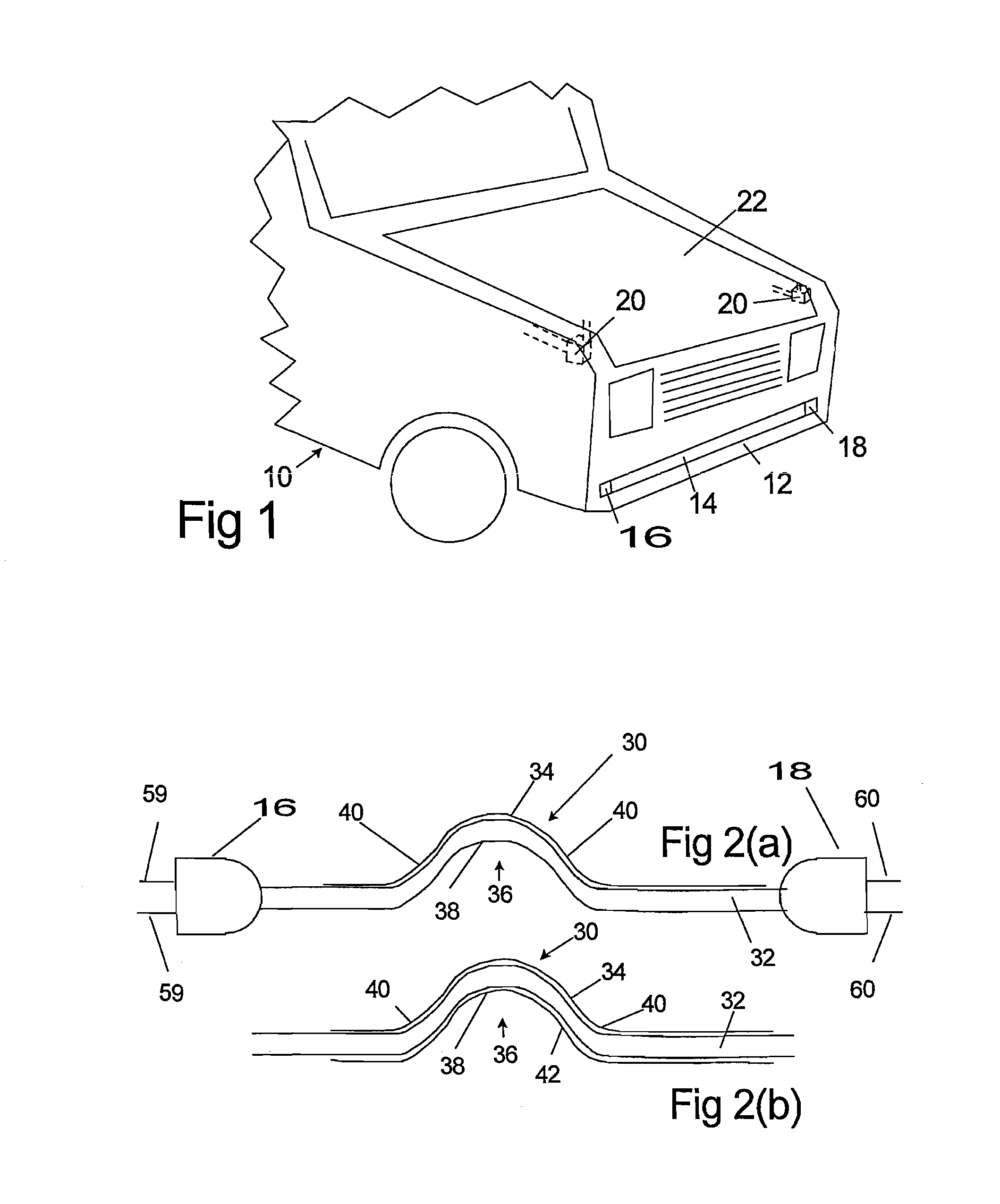
[0048]FIG. 1 illustrates the front end 10 of a vehicle having a bumper 12 extending across at the front. Attached to the bumper 12 is an optical fiber sensor array 14. In the particular arrangement shown, a light emitting source 16 and a light detector 18 are connected to the fiber or fibers in the array 14, one at each end. As described later light source 16 and light detector 18 can both be at the same end. The light source and light detector are connected to a control system (not shown) in the vehicle. Devices 20 are provided to “pop” or lift the hood 22, on receipt of a signal from the control system.

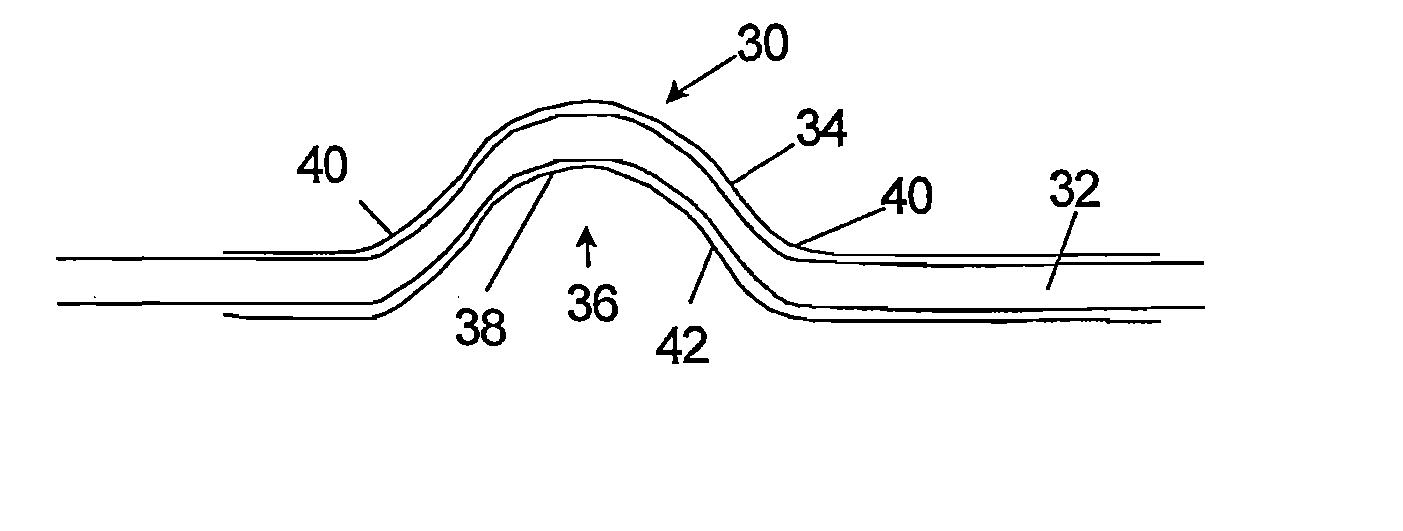
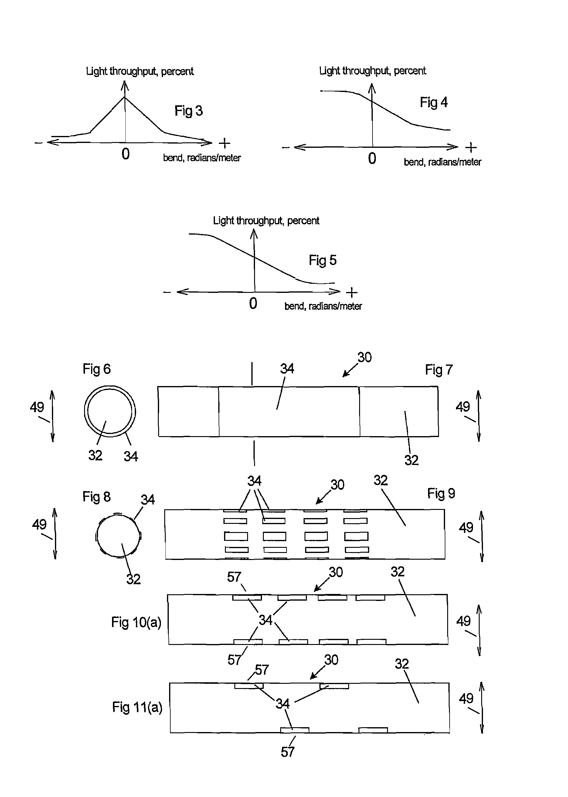
[0049] The invention provides various forms of optical fiber arrays and various forms of sensors for detecting, classifying and measuring inflected and non-inflected bends, their progression in time and to calculate shape, mass and velocity of intruding objects and also to identify such objects by shape, resilience, vibration and dampening. It is not necessarily a requirement that ...


PUM


Abstract

The invention relates to the apparatus for and a method of sensing impact between a vehicle and an object and particularly between a pedestrian and the front bumper (12) of a vehicle. An optical fiber array (14) extends along the bumper (12) and the array (14) has sensors spaced along the bumper (12). A sensor comprises light loss areas spaced peripherally and axially on a fiber. An impact distorts the sensors, modulating light transmitted along the fiber or fibers. A signal is produced which is processed by a signal processor and an output signal generated. The output signal is used to actuate a safety device, such as elevating the vehicle hood to increase clearance between hood and engine, to reduce the severity of any injuries.

Description

FIELD OF THE INVENTION [0001] This application is a continuation-in-part of U.S. patent application Ser. No. 11 / 228,304, filed on Sep. 19, 2005, which is a continuation of International Application No. PCT / CA04 / 00158, filed on Apr. 6, 2004. [0002] This invention relates to the sensing of impact between objects and a vehicle, and in particular to classification of the impacts to discern whether a pedestrian has impacted the front bumper of a vehicle. The invention also relates to the use of such sensing to actuate a safety device for the reduction of the severity of injury which may occur due to such impacts. BACKGROUND OF THE INVENTION [0003] It is an urgent requirement that the severity of injury to a pedestrian resulting from impact with a vehicle be reduced. A particular event such as a pedestrian being in impact with the bumper of a vehicle can result in serious head injuries by the head striking the hood. Although some deformation of the hood can occur, the degree of deformatio...

Claims


Application Information

Patent Timeline
Patent Type & Authority Applications(United States)
IPC IPC(8): E05F15/00B60K28/10G01J1/04B60R21/01
CPCB60R2021/01095B60R21/0136
Inventor DANISCH, LEE A.
Owner 059312 N B
Why Eureka
Try Eureka