Eureka AIR delivers breakthrough ideas for toughest innovation challenges, trusted by R&D personnel around the world.

Apparatus and methods for speed management and control

Active Publication Date: 2007-08-23
OMNITRACS
View PDF17 Cites 47 Cited by
  • Summary
  • Abstract
  • Description
  • Claims
  • Application Information

AI Technical Summary

Benefits of technology

[0006] To address one or more of the drawbacks of the prior art, the disclose

Problems solved by technology

Unfortunately, currently the only way for a driver to know the speed limit of a road is to observe posted speed limit signs, or to know the rules of a given city, area or type of road as to the speed limit when no signs are posted.
Posted speed limit signs are problematic because such signs may only be located infrequently on any given stretch of road.
Another disadvantage of such posted speed limit signs is that they are often obstructed from view by trees, shrubs and other signs.
Further, even if not obstructed, such speed limit signs may be difficult to see among the myriad of signs and advertisements typically found in urban and suburban areas.
Additionally, if a driver is new to a particular stretch of road, or is trying to find a location on the road, such posted speed limit signs may be outside of the driver's focus of attention and may be easily missed.
Thus, posted speed limit signs often provide less than adequate notice of the speed limit for that road to a driver of a vehicle.
Thus, many drivers lack knowledge of the rules of a given city, area or type of road as to the speed limit.
The disadvantage of these systems, however, is that the desired speed limit value will not change until manually altered or cancelled.
These cruise control systems do not include any mechanism to notify the driver of a speed limit of a road, or to automatically adjust the desired speed limit value based upon a change in the speed limit of the road.

Method used


Image

  • Apparatus and methods for speed management and control
  • Apparatus and methods for speed management and control
  • Apparatus and methods for speed management and control

Examples


Embodiment Construction

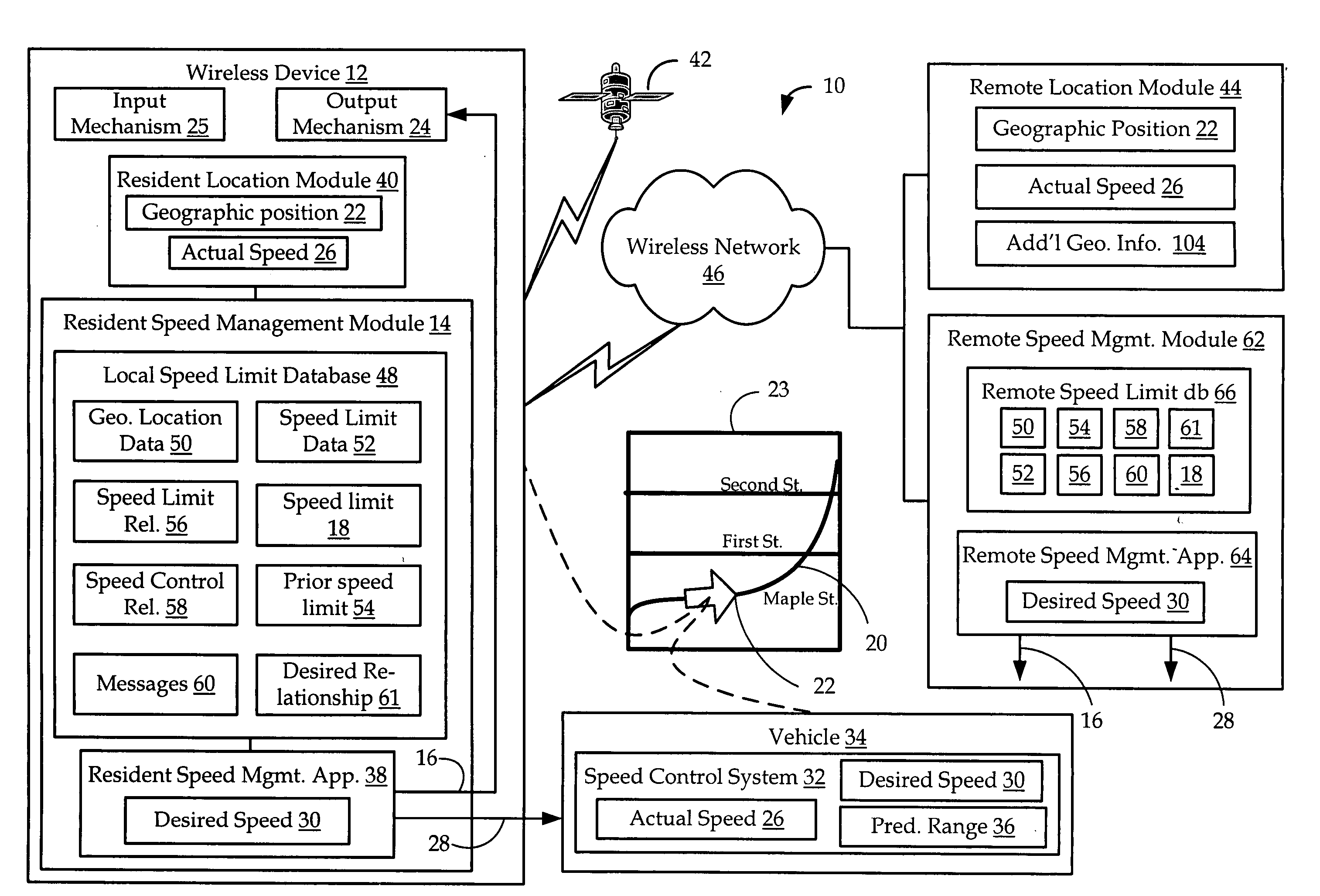
[0018] The disclosed embodiments include apparatus, methods and computer readable media for the management and control of a speed of movement associated with a wireless device. These apparatus and methods provide a wireless device with logic that enables the wireless device to automatically determine a speed limit of a transit route, such as a road, corresponding to the geographic position of the device. As such, the wireless device may generate an output to notify an end user of the speed limit, and may further generate speed control signals to automatically initiate a change in an actual speed associated with the wireless device, such as the speed of a vehicle carrying the wireless device.

[0019] Referring to FIGS. 1-3, one embodiment of a speed management and control system 10 includes a wireless device 12 having a resident speed management module 14 that determines a current speed limit 18 for a transit route 20 associated with a present geographic position 22 of the wireless de...


PUM


Abstract

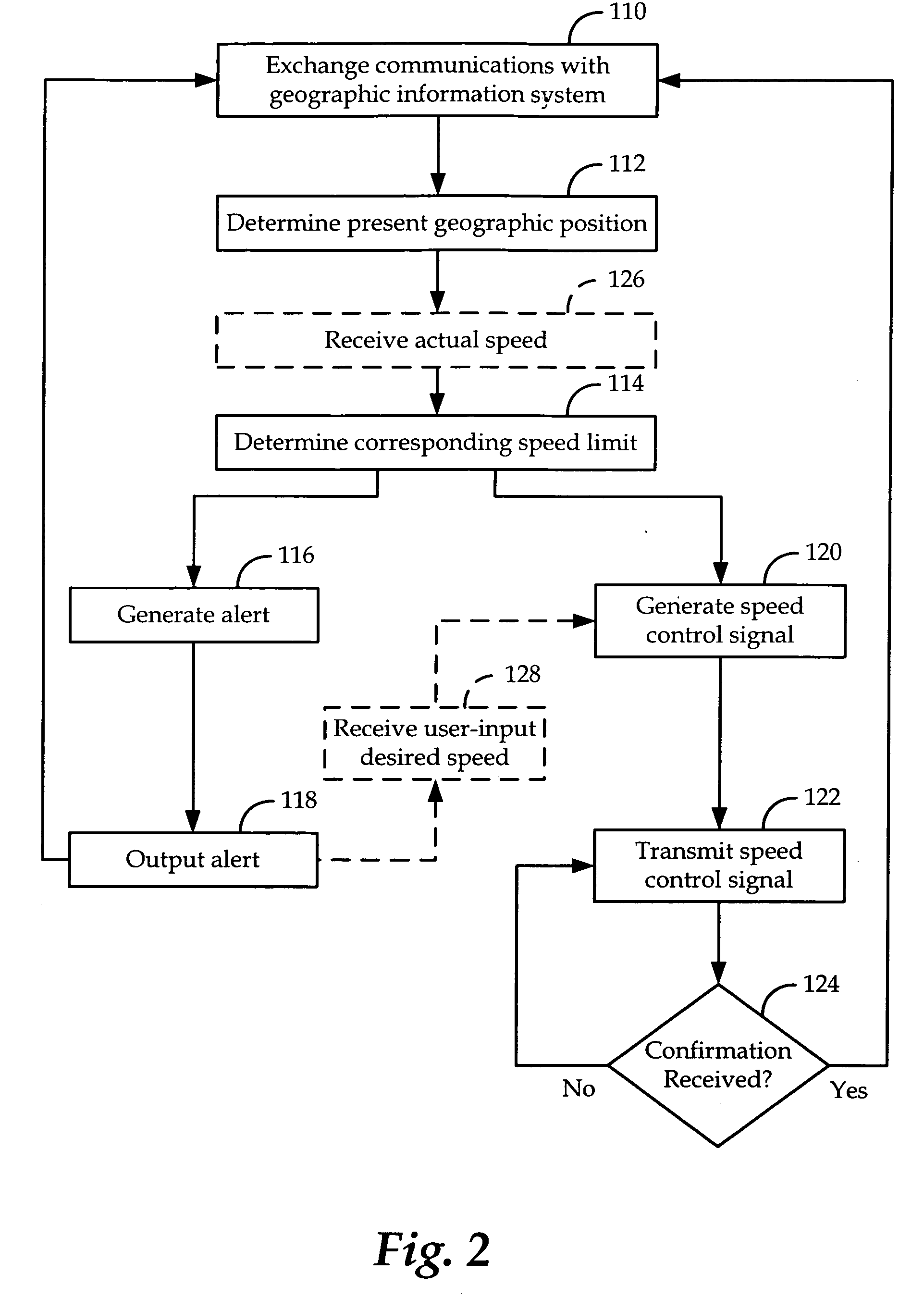
Apparatus, methods and computer readable media for speed management and control, including logic executable to determine a present geographic position of a wireless device, logic executable to determine a speed limit corresponding to the present geographic position, and logic executable to selectively generate an alert based upon the speed limit.

Description

FIELD OF THE INVENTION [0001] The disclosed embodiments relate to wireless devices and wireless communication networks, and more particularly, to apparatus and methods for speed management and speed control of a vehicle through a wireless device on a wireless network. BACKGROUND [0002] The driver of a vehicle should be aware of the speed limit of the road upon which they are driving. Unfortunately, currently the only way for a driver to know the speed limit of a road is to observe posted speed limit signs, or to know the rules of a given city, area or type of road as to the speed limit when no signs are posted. Posted speed limit signs are problematic because such signs may only be located infrequently on any given stretch of road. As such, a driver turning onto the road may not be notified of the speed limit in a timely manner. Another disadvantage of such posted speed limit signs is that they are often obstructed from view by trees, shrubs and other signs. Further, even if not obs...

Claims


Application Information

Patent Timeline
IPC IPC(8): B60T8/32
CPCB60K31/0058B60W2550/402G08G1/096791G08G1/096725G08G1/096716B60W2556/50G08G1/052
Inventor SHEYNBLAT, LEONID
Owner OMNITRACS
Why Eureka
Eureka Blog
Learn More