Heat exchanger
a heat exchanger and heat exchanger technology, applied in the direction of tubular elements, corrosion prevention, stationary conduit assemblies, etc., can solve the problems of affecting the heat exchanger's heat exchange performance, the heat pump cycle cannot operate normally, and the heat exchanger may freeze, so as to improve the heat exchange performance and water exchange performance. , the effect of high water exchange performan
- Summary
- Abstract
- Description
- Claims
- Application Information
AI Technical Summary
Benefits of technology
Problems solved by technology
Method used
Image

Examples
first embodiment
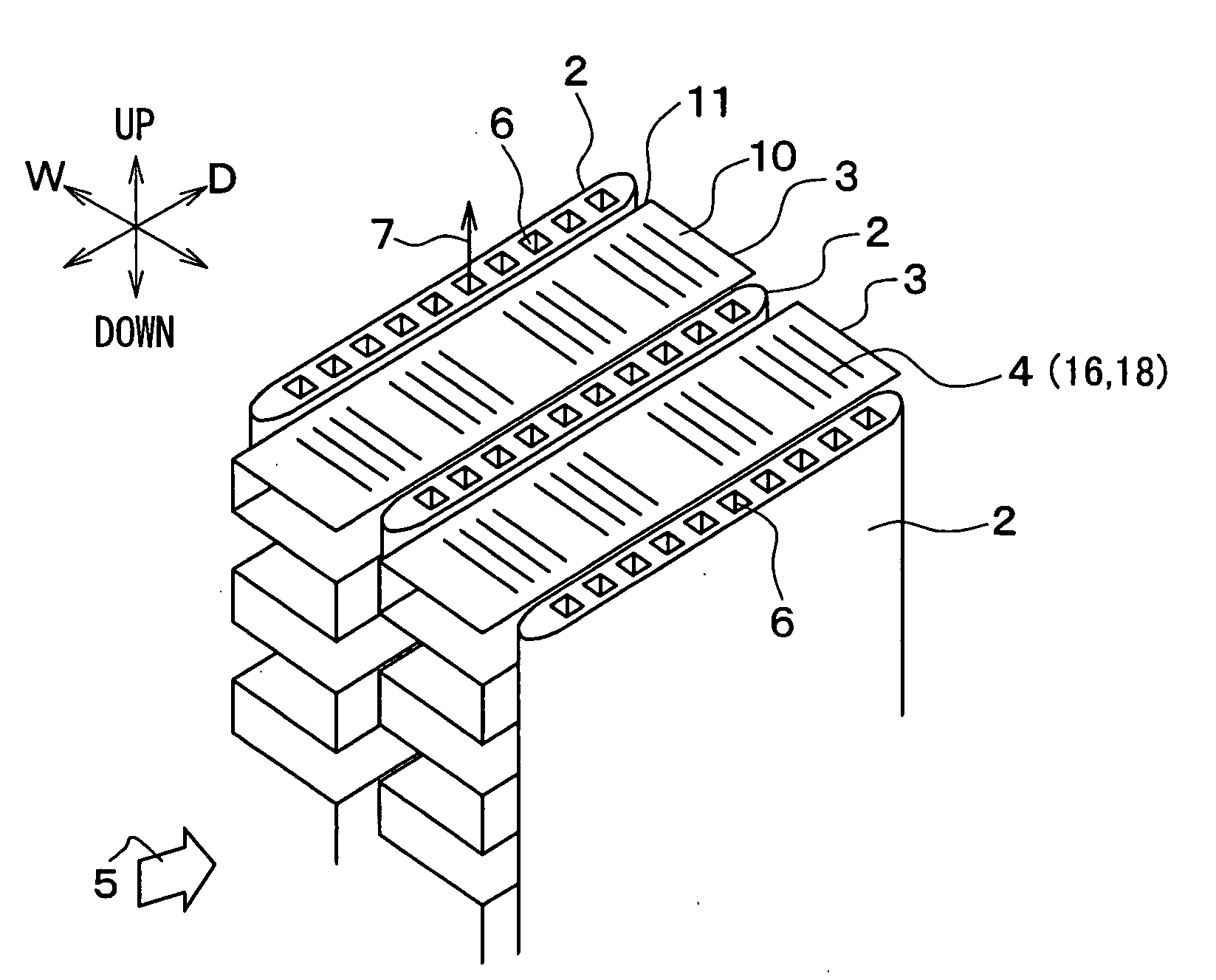
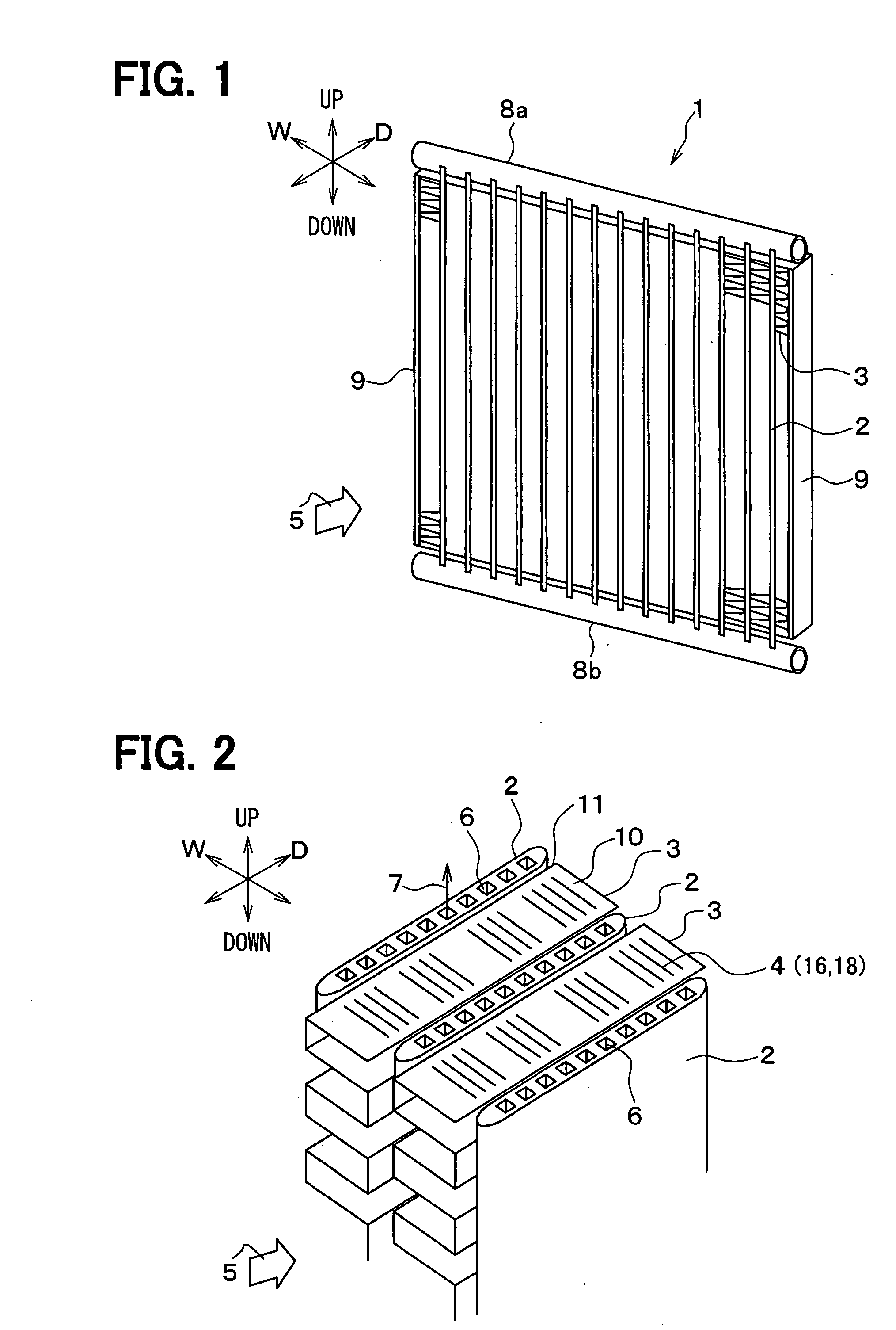
[0030]FIG. 1 shows a heat exchanger 1, which is suitably used for an outside heat-exchanging unit for a heat pump cycle, for example. As shown in FIGS. 1 and 2, the heat exchanger 1 includes plural flat tubes 2 and plural corrugated fins 3 disposed between the adjacent tubes 2. The tubes 2 are approximately in parallel to each other, and the fins 3 are connected to the tubes 2 to thermally contact the tubes 2. A blower (not shown) sends air 5 into space parts between the fins 3 and the tubes 2.
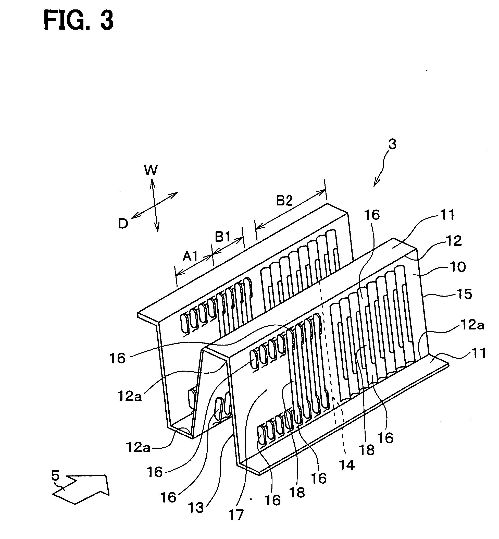
[0031]As shown in FIG. 2, the fin 3 has flat portions 10 and peak portions 11, which are alternately bent. The peak portions 11 are brazed to the tubes 2. A longitudinal direction of the flat portion 10 corresponds to a depth direction D of the fin 3 (i.e., a flow direction of the air 5). The flat portion 10 has louvers 4 (16, 18) extending in a width direction W of the fin 3, which is perpendicular to the fin depth direction D. In this embodiment, the fin depth direction D corresponds to a ma...
second embodiment
[0061]As shown in FIG. 10, only end louver areas A1, A2 are arranged on a flat portion 10 in a second embodiment. That is, the end louver area A1 is positioned at an upstream air side of the flat portion 10, and the end louver area A2 is positioned at a downstream side of the flat portion 10. Eight pairs of end louvers 16 are arranged on the end louver area A1, A2, and a flat (non-louver) part 17 is disposed between the end louvers 16 in the width direction W. The angle of the end louvers 16 relative to the flat portion 10 in the area A1 is opposite to that in the area A2. The other parts are made similar to the first embodiment.
[0062]According to the second embodiment, frost formed on the flat portion 10 can be reduced due to the flat part 17 without a louver. Therefore, the frosting time for normally operating the heat pump cycle can be relatively increased.
[0063]Further, the end louvers 16 are arranged in the depth direction D approximately from an upstream end 13 to a downstream...
third embodiment
[0064]As shown in FIG. 11B, a dimension of a corrugated fin 3 in the depth direction D is longer than that of a tube 2 in a third embodiment. A downstream end 15 of the fin 3 corresponds to a downstream end of the tube 2, and an upstream end 13 of the fin 3 is protruded from an upstream end 22 of the tube 2 toward the upstream air side so as to form a protrusion 21. The protrusion 21 is formed by extending the flat portion 10, and has a flat (non-louver) part 17 thereon. Any end louver 16 is not arranged on the protrusion 21, because the protrusion 21 is not in contact with the tube 2.
[0065]As shown in FIG. 11A, an end louver area A2 is positioned at a downstream air side on the flat portion 10, and two full louver areas B1, B2 are positioned between the end louver area A2 and the flat part 17 (protrusion 21).
[0066]A height h1 of the end louver 16, a height h2 of an aperture formed by the end louver 16 and a height h3 of a center louver 18 are made similar to the first embodiment. F...
PUM
 Abstract
Description
Claims
Application Information
 - R&D
- Intellectual Property
- Life Sciences
- Materials
- Tech Scout
- Unparalleled Data Quality
- Higher Quality Content
- 60% Fewer Hallucinations
Browse by: Latest US Patents, China's latest patents, Technical Efficacy Thesaurus, Application Domain, Technology Topic, Popular Technical Reports.
© 2025 PatSnap. All rights reserved.Legal|Privacy policy|Modern Slavery Act Transparency Statement|Sitemap|About US| Contact US: help@patsnap.com