
Motor vehicle door latch

a technology for motor vehicles and latches, applied in the direction of building locks, fastening means, dampening of movement of lock parts, etc., can solve the problems of generated noise and still present a problem, and achieve the effect of facilitating undampened movement, reliable functioning, and reducing nois

Inactive Publication Date: 2007-08-30
KIEKERT AG
View PDF9 Cites 10 Cited by
  • Summary
  • Abstract
  • Description
  • Claims
  • Application Information

AI Technical Summary

Benefits of technology

[0010]In this way it is prevented that in case of excess damping at the beginning of the clothing path, the pawl does not correctly engage in the primary position of the catch and that the catch is so to speak “missed”. This is a clear improvement over conventional latches. This is also of special significance if the catch is in its so-called “overtravel position” on the other side of the primary position and returns back from that position. In most cases the overtravel position of the catch is assumed against the force of an additional damping element, returning back the catch into the primary position and / or the first position.
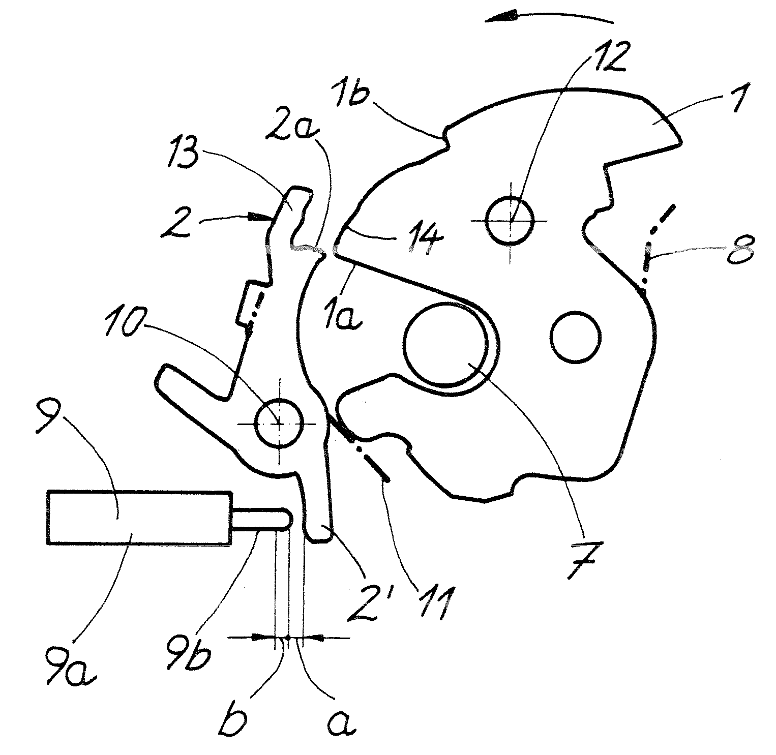
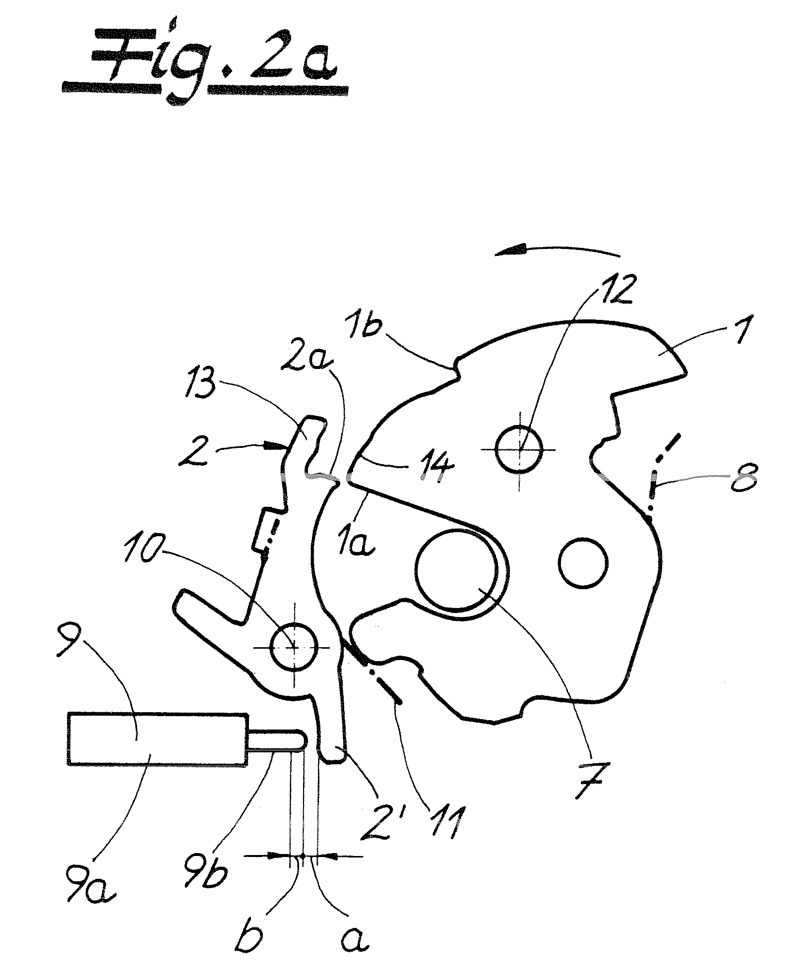
[0011]Depending on how quickly the catch moves during this process (assisted by additional spring forces moving the catch into its “open” position), it may happen that the catch has already moved past the pawl, before it has engaged in the primary position. In order to avoid this under all circumstances, the invention teaches that the damping element only enter into a dampened engagement with the closing path of the locking mechanism once a catch position—in most cases the primary position—has been reached. The damping element then ensures a further dampened engagement of the pawl in the primary position and that a “hard” mechanical stop and noises associated therewith are avoided.
[0012]The end of the closing path of the locking mechanism is generally not limited by the damping element. Although the damping element could in principle also function as an end stop, the invention teaches an end stop independent from the damping element wherein the end stop by itself mechanically limits the closing path of the locking mechanism. In this way it is ensured that in the end position (the position at the end of the closing path) no potential counter-forces produced by the damping element act between the pawl and the catch.
[0015]Generally, the damping element comprises at least one damping fluid and / or is provided with at least one damping material. A plunger or a lever interacts with the damping fluid and / or the damping material, whose movement is dampened and which also interacts with the locking mechanism. In most cases the damping element actually acts on the pawl, although in certain embodiments of the invention the damping element acts additionally or alternatively on the catch. As soon as the pawl or the catch enters the range of action of the damping element, their closing movement is restrained and slowed down, depending on the stipulated selected damping constant. As a result, a hard mechanical impact at the end of the closing path is avoided as well as it is avoided that parts rub or scrape along each other. Noise is consequently reduced.
[0017]As a result, a motor vehicle door latch is provided which, on one hand ensures a reliable functioning, in particular, when the pawl enters the primary position and which, on the other hand, provides perfect noise dampening.

Problems solved by technology

The state of the art is not fully satisfactory, however, as rubber dampers used in most cases do not always guarantee that the pawl engages securely in the catch.
The generated noise also still presents a problem.

Method used


Image

  • Motor vehicle door latch
  • Motor vehicle door latch
  • Motor vehicle door latch

Examples


Embodiment Construction

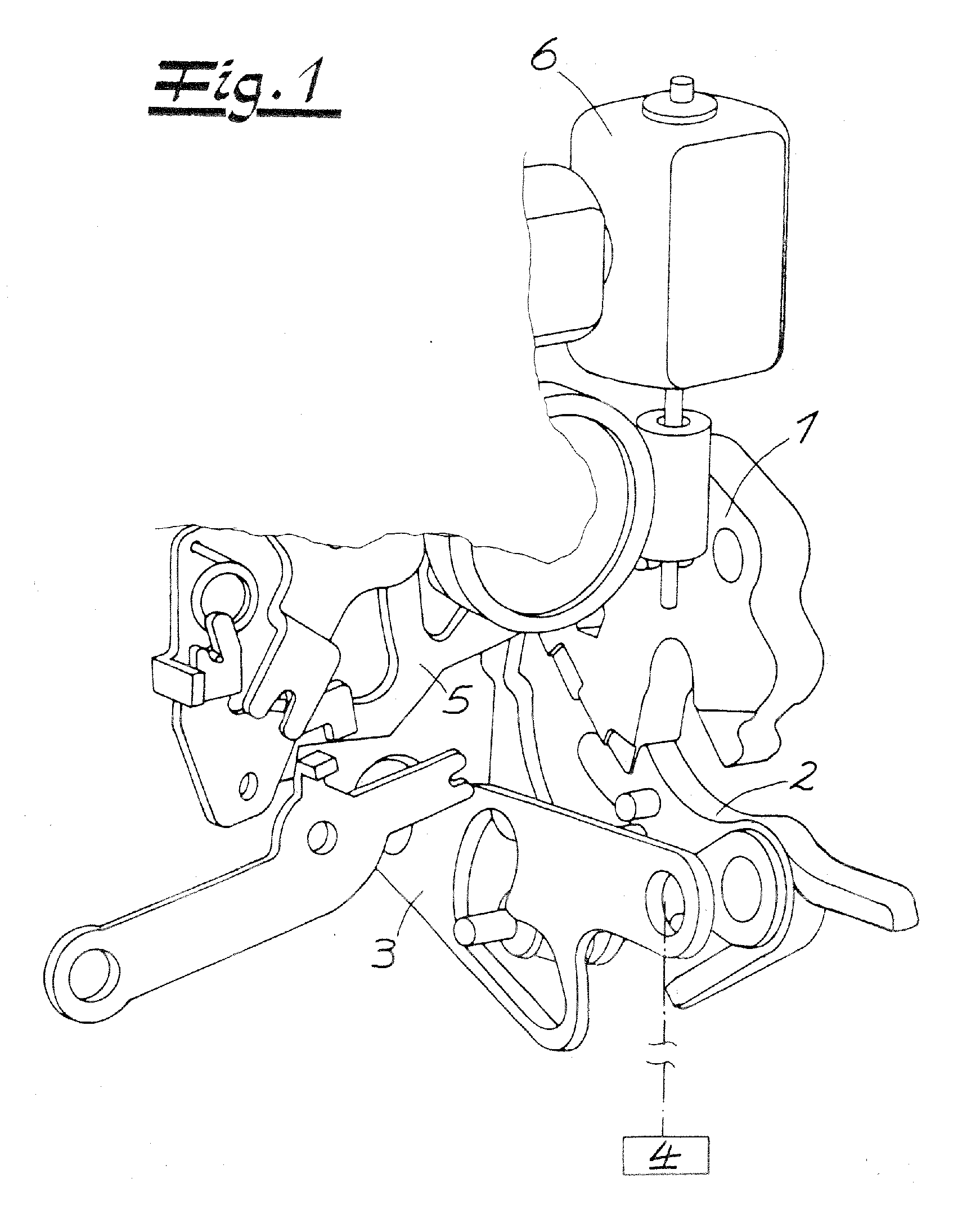
[0023]FIG. 1 shows a motor vehicle door latch with a locking mechanism 1, 2 comprising a catch 1 and a pawl 2. Also apparent from the figure is a release lever 3, disengaging the pawl 2, which release lever 3 can be connected to a handle 4.—The figure shows a partial view of a central locking lever 5, operated by a motor 6. Depending on the position of the central locking lever 5, i.e., “unlocked” or “locked,” the pawl 2 can or cannot be disengaged with the aid of the handle 4, respectively.

[0024]FIGS. 2a to 2c show the details of the locking mechanism 1, 2 interacting with a closing bolt 7. During the closing of an associated motor vehicle door, a lid or a similar device, the closing bolt 7 initially moves the catch 1 by turning clockwise around axis 12 to its overtravel position as indicated in FIG. 2a. As a result of being in this overtravel position, a gap in the direction of the circumference is visible between a primary position 1a and / or the associated stop surface and a bloc...


PUM


Abstract

Taught is a motor vehicle door latch with a locking mechanism (1, 2) comprising a catch (1) and a pawl (2), said locking mechanism (1, 2) being capable of being moved along at least a first pathway and a second pathway; and at least one damping element (9), said damping element having at least a first damper constant and a second damper constant; wherein said damping element (9) is capable of damping a movement of said locking mechanism (1, 2) along said first pathway with said first damper constant; and said damping element (9) is capable of damping a movement of said locking mechanism (1, 2) along said second pathway with said second damper constant.

Description

CROSS-REFERENCE TO RELATED APPLICATIONS[0001]Pursuant to 35 U.S.C §119 and the Paris Convention Treaty, this application claims the benefit of German Patent Application No. DE 10 2006 006 443 filed Feb. 10, 2006, the contents of which are incorporated herein by reference.BACKGROUND OF THE INVENTION[0002]1. Field of the invention[0003]The invention relates to a motor vehicle door latch with a locking mechanism comprising a catch and pawl and at least one damping element for the locking mechanism.[0004]2. Description of the Related Art[0005]A motor vehicle door latch with a locking mechanism comprising a catch and pawl is known in the art and described, for example, in UK Patent Application Publication No. GB 2 321 928 A. A damping stop for the catch is also known and described, for example, in German Patent Application Publication No. DE 103 20 457 A1. In addition, sound damping devices for door latches that are disposed between a catch and a pawl are known and described, for instanc...

Claims


Application Information

Patent Timeline
IPC IPC(8): E05C3/06
CPCE05B77/42E05B85/26Y10T292/1082
Inventor WESTERWICK, VOLKERHANISCH, DIRKSCHIFFER, HOLGER
Owner KIEKERT AG
Learn More