Optical data synchronization scheme

a synchronization scheme and optical data technology, applied in multiplex communication, electrical equipment, selection arrangements, etc., can solve problems such as problems such as problems such as problems such as problems such as problems such as no equivalent elastic buffering device, packets present challenges, and problems such as problems

Active Publication Date: 2007-08-30
CISCO TECH INC
View PDF27 Cites 20 Cited by
  • Summary
  • Abstract
  • Description
  • Claims
  • Application Information

AI Technical Summary

Benefits of technology

[0006] Asynchronous optical data is aligned with synchronous convergence,points in an optical packet switching system. The convergence points can be any place where data enters an optical packet switching element, buffer stage, switch fabric, etc. The arrival time for data approaching the convergence point is compared with a reference signal associated with the upcoming convergence point. The comparison is used to identify the amount of time-shift required to...

Problems solved by technology

Optically switching packets presents challenges that may not exist in electronic packet switching equipment.
However, in optical switching architectures there are no equivalent elastic buffering devices.
Thus, problems can arise when one or more asynchronous packet streams converge at some synchronous processing point (a.k.a., convergence point).
Unfortunately, optical buffers are typically synchronous...

Method used


Image

  • Optical data synchronization scheme
  • Optical data synchronization scheme
  • Optical data synchronization scheme

Examples


Embodiment Construction

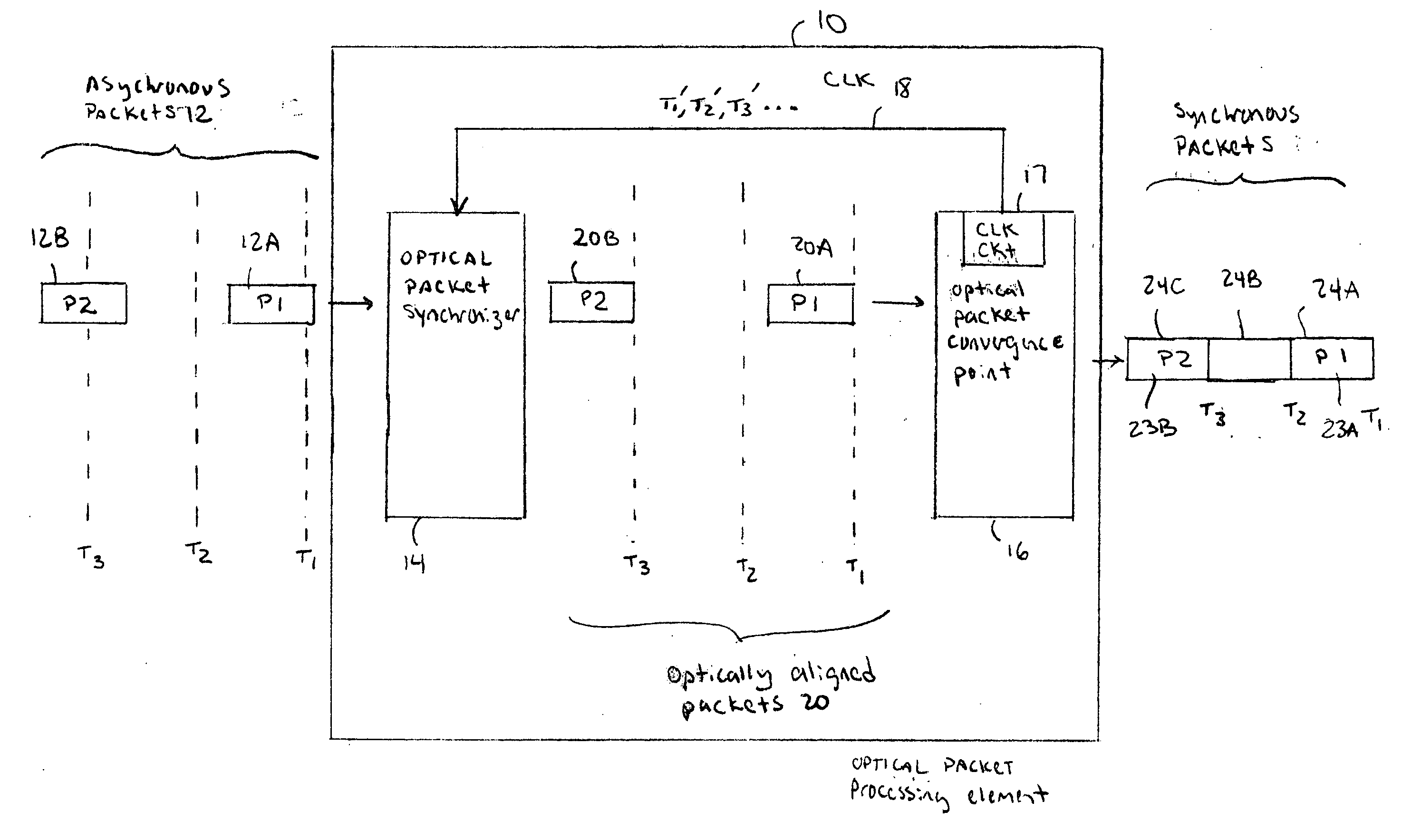
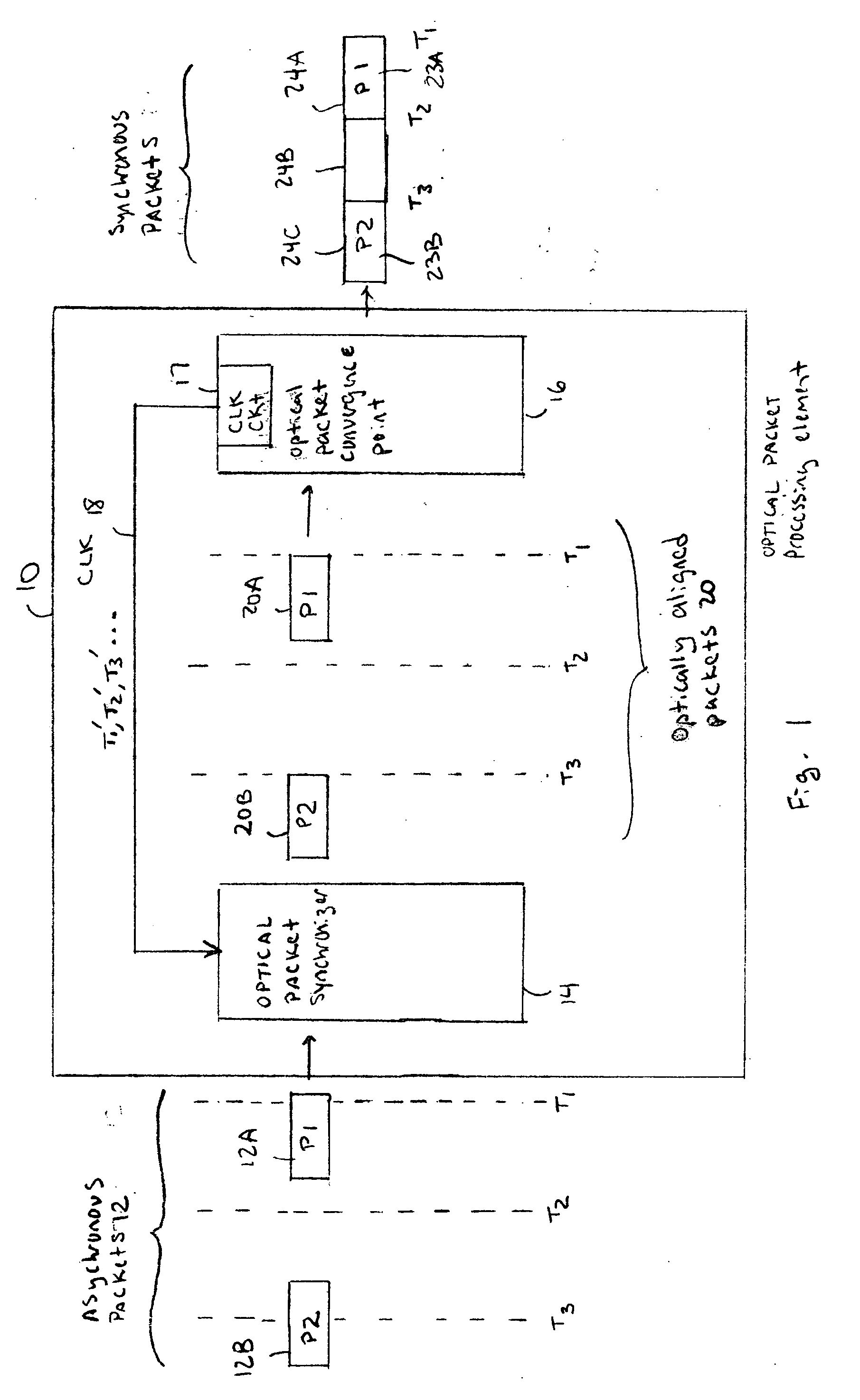
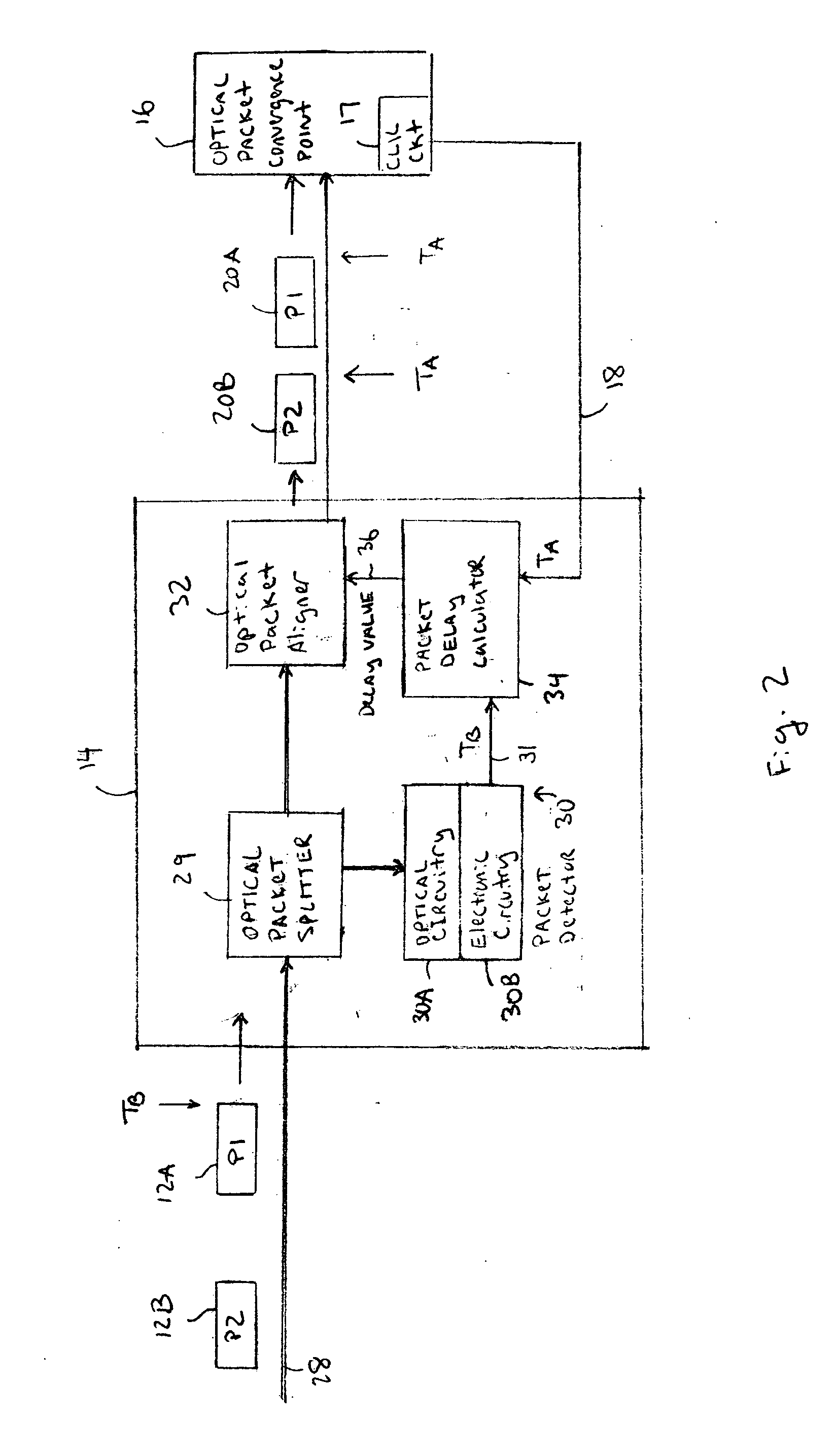
[0015] The area of optical packet switching focuses almost entirely on device-level research. Usually, there is discussion of the blocks required to make a system, without any practical solutions as to how to resolve the problem of gluing different optical components together. The optical packet synchronizer described below provides a system solution for handling asynchronous data in an optical packet processing system.

[0016] It should be understood that the optical packet synchronizer described below can be used in any optical processing device with one or more convergence points that requires synchronous optical data processing of asynchronously received optical data. Optical processing devices using the optical packet synchronizer can be any type of optical packet switch, router, gateway, head-end, firewall, Digital Subscriber Loop (DSL), Time Division Multiplexing (TDM), Asynchronous Transfer Mode (ATM) device, etc. However, for simplicity, the examples below will refer to any ...


PUM


Abstract

Asynchronous optical data is aligned with synchronous convergence points in an optical packet switching system. The convergence points can be any place where data enters an optical packet switching element, buffer stage, switch fabric, etc. The arrival time for data approaching the convergence point is compared with a reference signal associated with the upcoming convergence point. The comparison is used to identify the amount of time-shift required to align the approaching data with the reference signal. Control information is derived according to the comparison and used to control an optical data aligner that synchronizes the data with the convergence point.

Description

BACKGROUND [0001] Optical packet switches and routers process packets in an optical domain. Optically switching packets presents challenges that may not exist in electronic packet switching equipment. For example, packets can arrive asynchronously on various input links on the packet switching device. In an electronic router, the data is synchronized relatively easily link interface. For example, the asynchronously arriving packets can be stored in a First In-First Out (FIFO) buffer while waiting for subsequent packet processing. Packets are written into the FIFO when they arrive and are read only when the downstream packet processing stage is ready. [0002] However, in optical switching architectures there are no equivalent elastic buffering devices. Thus, problems can arise when one or more asynchronous packet streams converge at some synchronous processing point (a.k.a., convergence point). In one example, the convergence point could be, but is not limited to, a synchronous switch...

Claims


Application Information

Patent Timeline
IPC IPC(8): H04B10/00
CPCH04J14/0227H04Q11/0005H04Q11/0066H04Q2011/002H04J14/0241H04Q2011/0041H04Q2011/0045H04Q2011/005H04J14/0238H04Q2011/0032
Inventor EPPS, GARRYCOHEN, EARL T.
Owner CISCO TECH INC
Why Eureka
Try Eureka