
Detectable warning plate

Inactive Publication Date: 2007-08-30
EAST JORDAN IRON WORKS
View PDF12 Cites 25 Cited by
  • Summary
  • Abstract
  • Description
  • Claims
  • Application Information

AI Technical Summary

Benefits of technology

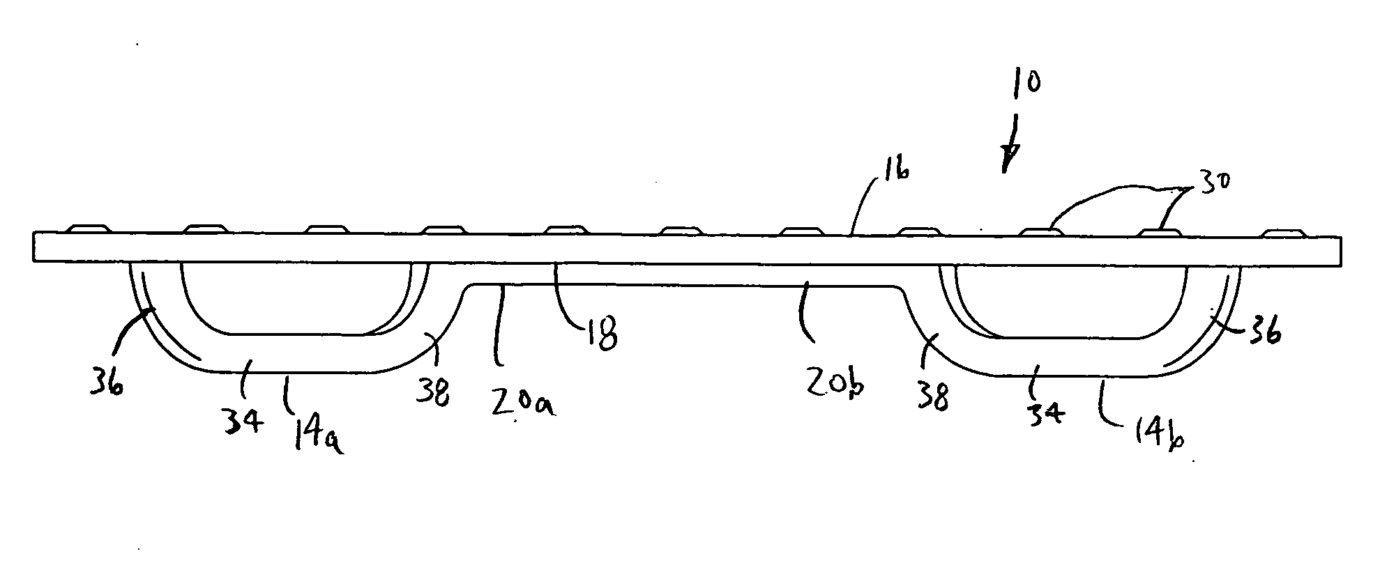
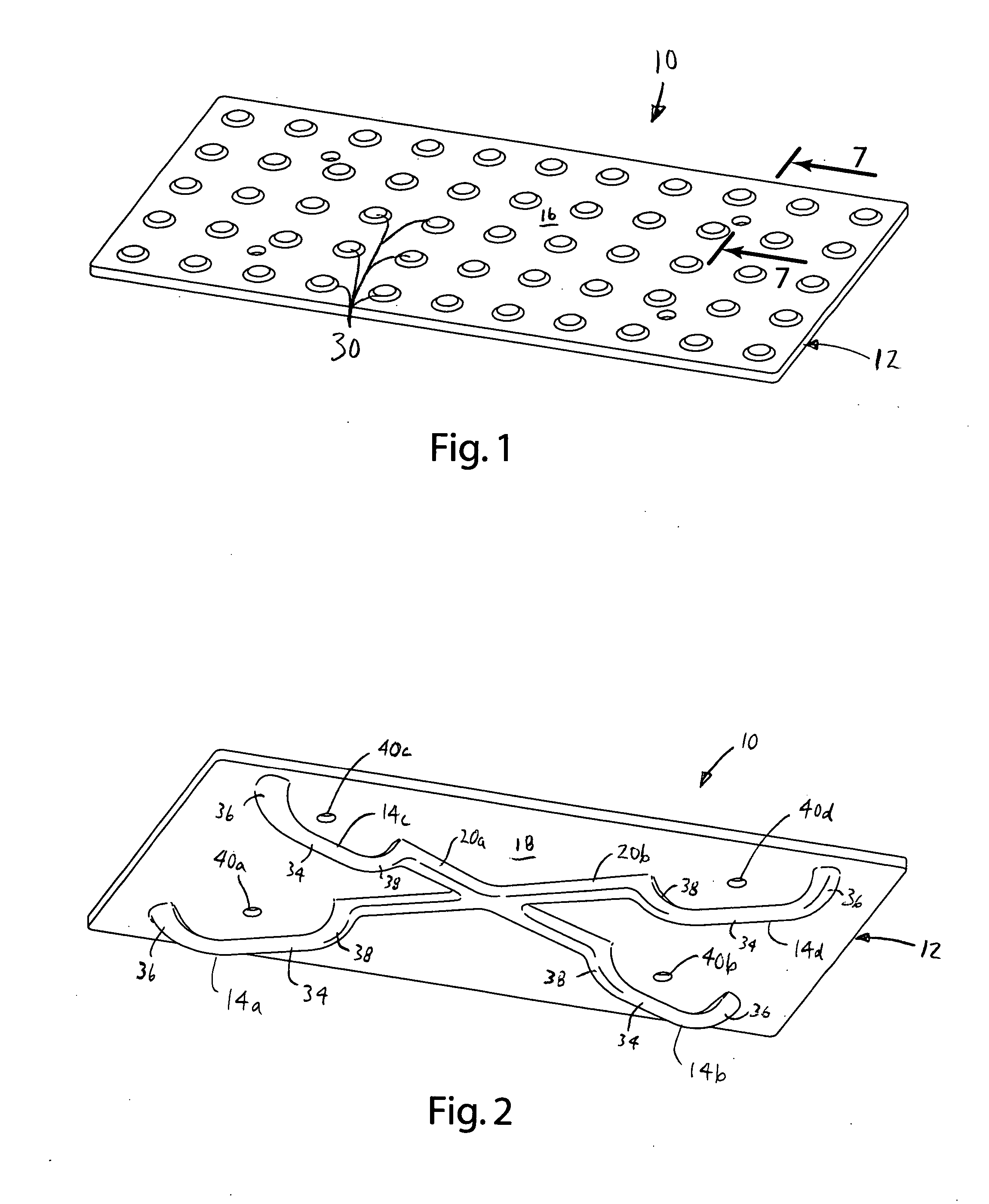
[0007] In another embodiment, the plate includes support ribs to strengthen the plate and, among other things, reduce the possibility of warping or other deformation during manufacture. In one embodiment, the support ribs extend from the undersurface of the plate and extend around the plate near its periphery. In another embodiment, the support ribs are arranged in an X-shaped configuration with its intersection located at the approximate center of the plate. In these embodiments, the lugs may be extensions of the support rib.
[0009] The present invention provides a detectable warning plate that is durable and easy to install. The lugs provide an integral structure that can be embedded within concrete to provide a durable and lasting attachment. The broad spacing of the lugs permits wet concrete to easily flow around the lugs to interlock the plate and the concrete. The vent holes facilitate installation by permitting air trapped within the lugs to escape as the wet concrete flows around the lugs. Otherwise, air pockets trapped under the plate might have a significant adverse impact on the interlock between the plate and the concrete. The integral support ribs dramatically reduce the risk of warping during manufacture and may provide additional structure for the lugs.

Problems solved by technology

Unfortunately, it can be difficult to manufacture protrusions in concrete that are uniform and of consistently high quality.
Further concrete protrusions are highly susceptible to wear and other damage.
Experience has revealed that detectable warning products manufactured from plastics, composites and other relatively light materials are more susceptible to wear and more prone to damage from snow plows and other maintenance equipment.
Further, conventional detectable warning products of essentially all types can be susceptible to separation from the concrete in which they are embedded.
For example, external forces, such as a snow plow, may break the detectable warning plate away from the concrete.
Further, the expansion and contraction associated with temperature changes can also cause a detectable warning plate to separate from the concrete.
It can, however, be difficult to get the concrete to adequately flow around the interlocking structure and these conventional efforts have met with only limited success.

Method used


Image

  • Detectable warning plate
  • Detectable warning plate
  • Detectable warning plate

Examples


Embodiment Construction

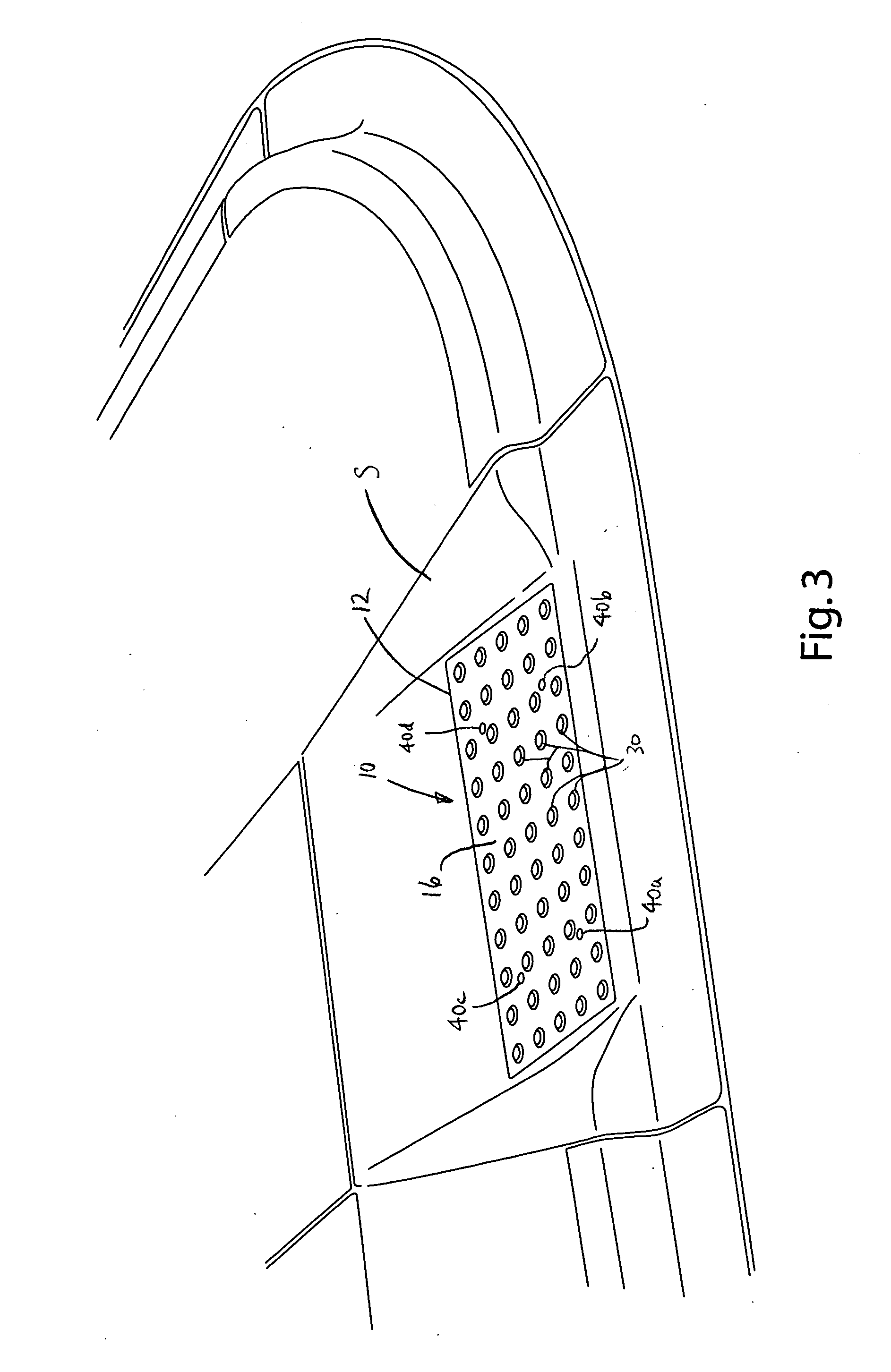
[0026] A detectable warning plate in accordance with an embodiment of the present invention is shown in FIGS. 1 and 2, and is generally designated 10. The detectable warning plate 10 generally includes a main body 12 and a plurality of lugs 14a-d that extend from the undersurface of the plate 10. As perhaps best shown in FIG. 3, the detectable warning plate 10 may be installed in sidewalks S, walkways and other similar structures to signal the end of the sidewalk to the blind. During installation, the lugs 14a-d are embedded in wet concrete to lock the plate 10 in place within the concrete. If desired, a plurality of detectable warning plates 10 may be installed adjacent to each other to provide a warning area of the desired size.

[0027] Referring now to FIGS. 1, 2 and 4, the detectable warning plate 10 generally includes a main body 12 and a plurality of lugs 14a-d. In the illustrated embodiment, the main body 12 is a generally rectangular plate. However, its shape may vary from ap...


PUM


Abstract

A detectable warning plate having integrally cast lugs. The lugs may extend from the undersurface of the plate so that they can be entrapped within concrete during installation. The plate may define a vent hole through the plate above each lug to permit air to escape from beneath the dome plate during installation. The plate may include one or more integral support ribs that extend downwardly from the plate. The support ribs may extend around the plate near the periphery. The lugs may be extensions of the support ribs.

Description

BACKGROUND OF THE INVENTION [0001] The present invention relates to municipal / construction castings and more particularly to detectable warning plates. [0002] Detectable warning plates are widely used as a tactile warning for the blind in sidewalks, walkways and other similar structures. Typically, detectable warning plates are embedded in the sidewalk and have an upper surface with an arrangement of regularly-spaced protrusions in the shape of truncated domes. The size, shape and arrangements of protrusions are specified in the ADA Accessibility Guidelines for Detectable Warnings. These specifications are intended to provide uniform warnings that can be readily detected by the blind. In some applications, the prescribed pattern of protrusions is formed directly in the concrete. Unfortunately, it can be difficult to manufacture protrusions in concrete that are uniform and of consistently high quality. Further concrete protrusions are highly susceptible to wear and other damage. [000...

Claims


Application Information

Patent Timeline
IPC IPC(8): E01C11/24
CPCE01C11/24
Inventor VELDBOOM, LEA M.SNYDOR, JOHN H.HOLT, KORMNA M.WEBB, DENNIS E.JOHNSON, JEREMYLOVISKA, TODD C.RACHWNZ, BRIAN J.BEAL, SCOTT B.
Owner EAST JORDAN IRON WORKS
Learn More