

Light guide plate and manufacturing method of light guide plate pattern
a manufacturing method and technology applied in the field of light guide plate, can solve the problems of long development period and no efficiency, considerable cost of molds to be spent during product development period, etc., and achieve the effect of efficient integral design, low cost and less time-consuming
- Summary
- Abstract
- Description
- Claims
- Application Information
AI Technical Summary
Benefits of technology
Problems solved by technology
Method used
Image

Examples
Embodiment Construction
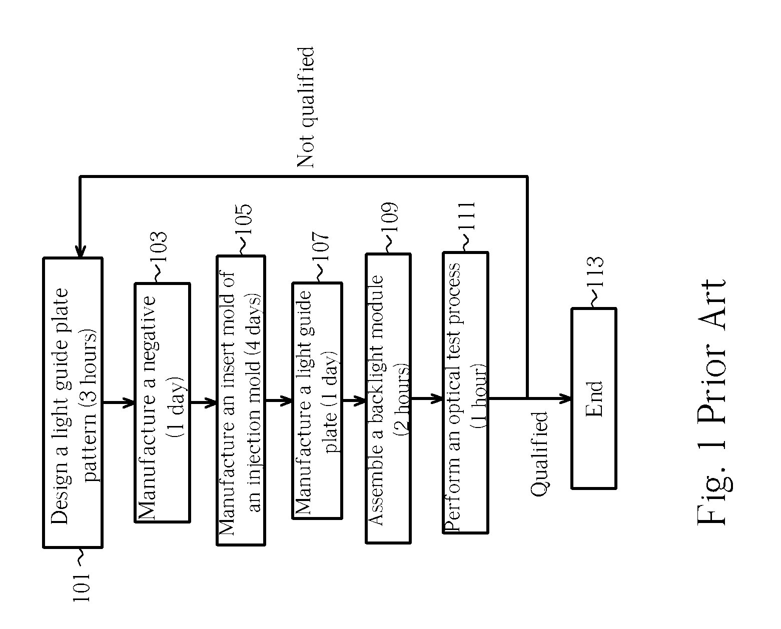
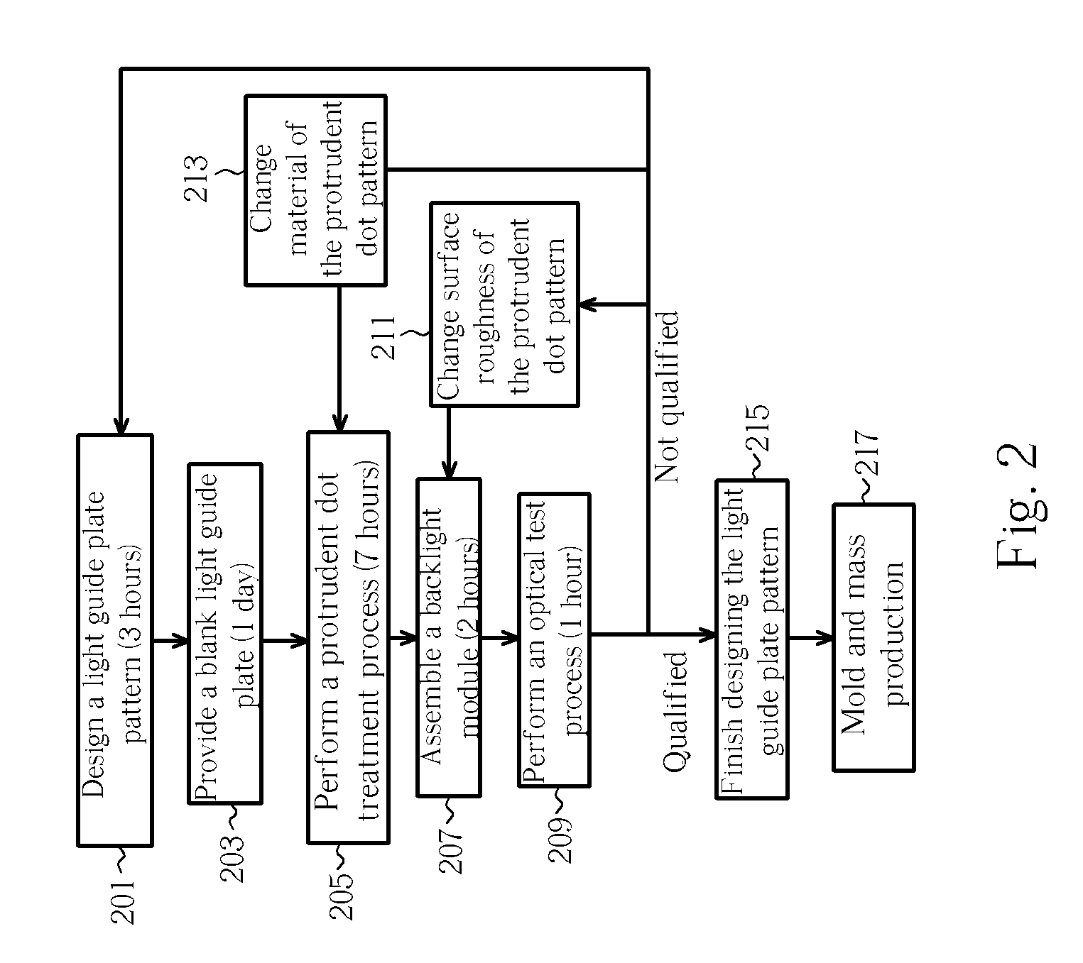
[0027] Please refer to FIG. 2. FIG. 2 is a flowchart of a method of designing and manufacturing a light guide plate pattern according to the present invention. In the present invention, the light guide plate is applied in a flat display such as a LCD. According to the present invention, a flowchart of the method of designing and manufacturing a light guide plate pattern is as follows.
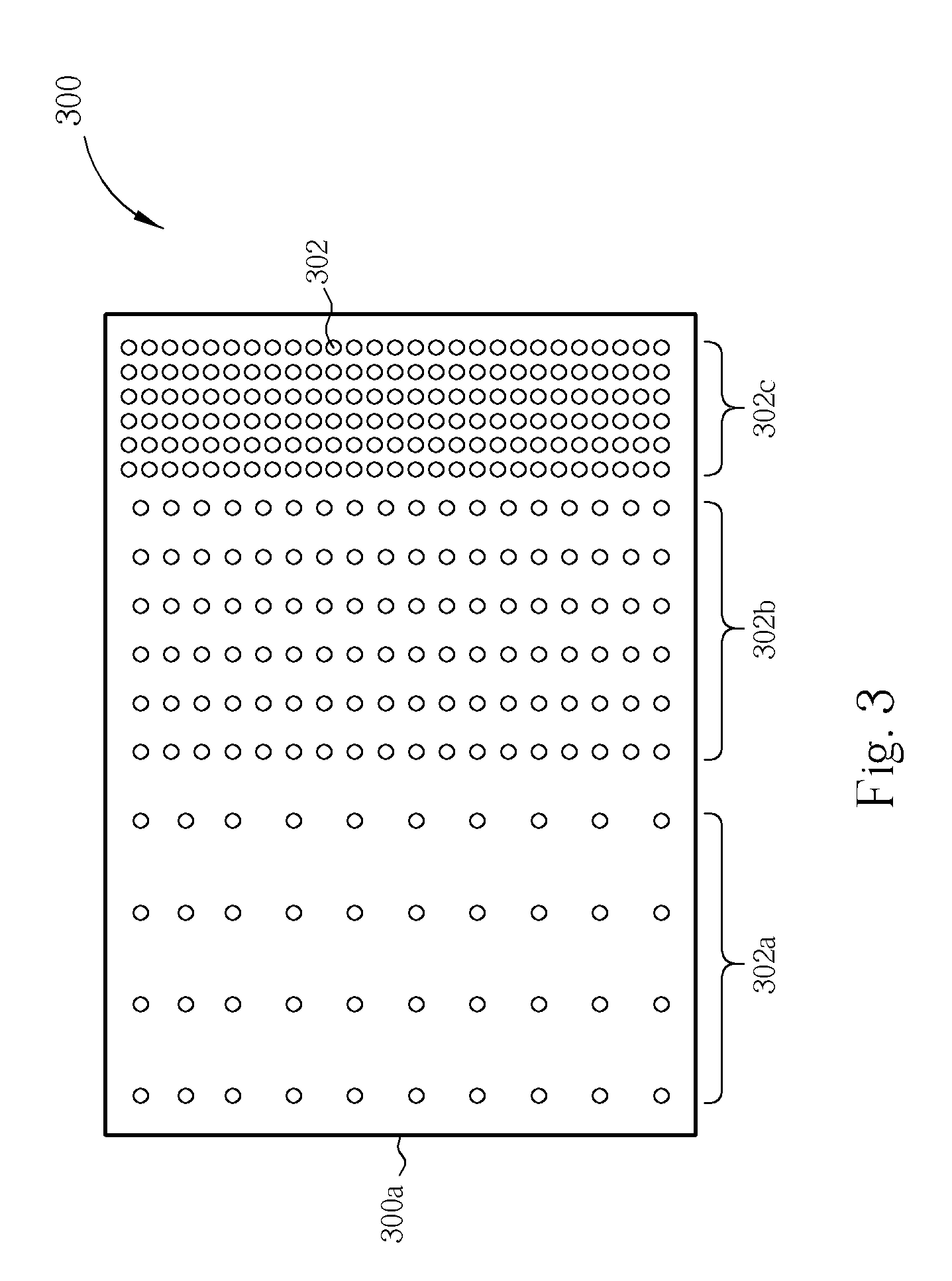
[0028] Step 201: According to the developing product, design a light guide plate pattern comprising plurality of protrudent dot patterns, and the designing time is about 3 hours, and then go to step 203;
[0029] Step 203: Provide at least a blank light guide plate with a smooth surface, wherein the blank light guide plate can be manufactured by injection molding process, and the manufacturing time of the blank light guide plate is about 1 day, and then go to step 205;
[0030] Step 205: Perform a protrudent dot treatment process on the blank light guide plate surface according to the light guide plate pat...
PUM
 Abstract
Description
Claims
Application Information