An electromagnetic induction phenomenon demonstration device

A demonstration device and electromagnetic induction technology, which is applied in the field of physics teaching experiments, can solve problems such as the inability to clearly and intuitively demonstrate the induced current, the structure of the demonstration instrument is too simple, and the experimental effect is not ideal, so as to improve the teaching effect, the effect is clear, intuitive, and easy. understand the effect

Inactive Publication Date: 2019-08-30
汪少斌
View PDF14 Cites 0 Cited by
  • Summary
  • Abstract
  • Description
  • Claims
  • Application Information

AI Technical Summary

Problems solved by technology

It not only reveals the inner connection between electricity and magnetism, but also lays the experimental foundation for the mutual conversion between electricity and magnetism, and opens up the way for human beings to obtain huge and cheap electric energy. Students who are new to this knowledge point are often difficult to understand. If you do not use teaching demonstration equipment, but only rely on language or gestures, students are often not easy to master. The structure of general teaching equipment is too simple, and often the experimental results are not ideal. For example, the application number is 201710362031.5 announced an "Electromagnetic Induction Phenomenon Demonstration Apparatus", including brackets, coils, magnets, and wires. The structure of this demonstration apparatus is too simple to demonstrate the generation of induced current clearly and intuitively. It needs further explanations from the instructor's language and cleaning. The experiment The effect is not ideal, so a new type of electromagnetic induction phenomenon demonstration device is needed

Method used


Image

  • An electromagnetic induction phenomenon demonstration device
  • An electromagnetic induction phenomenon demonstration device
  • An electromagnetic induction phenomenon demonstration device

Examples


Embodiment Construction

[0016] The present invention will be further described below in conjunction with specific embodiments. The exemplary embodiments and descriptions of the present invention are used to explain the present invention, but not as a limitation to the present invention.

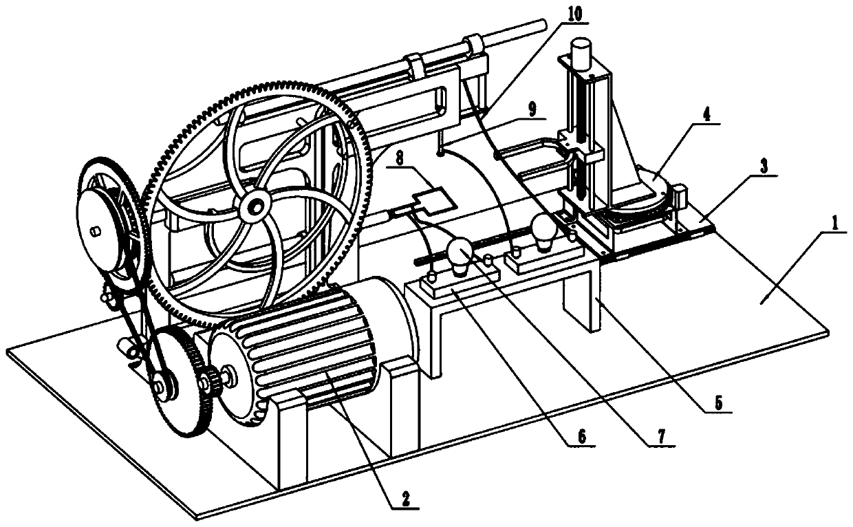
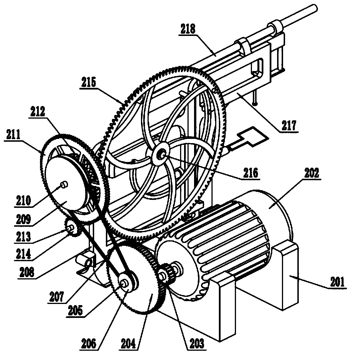
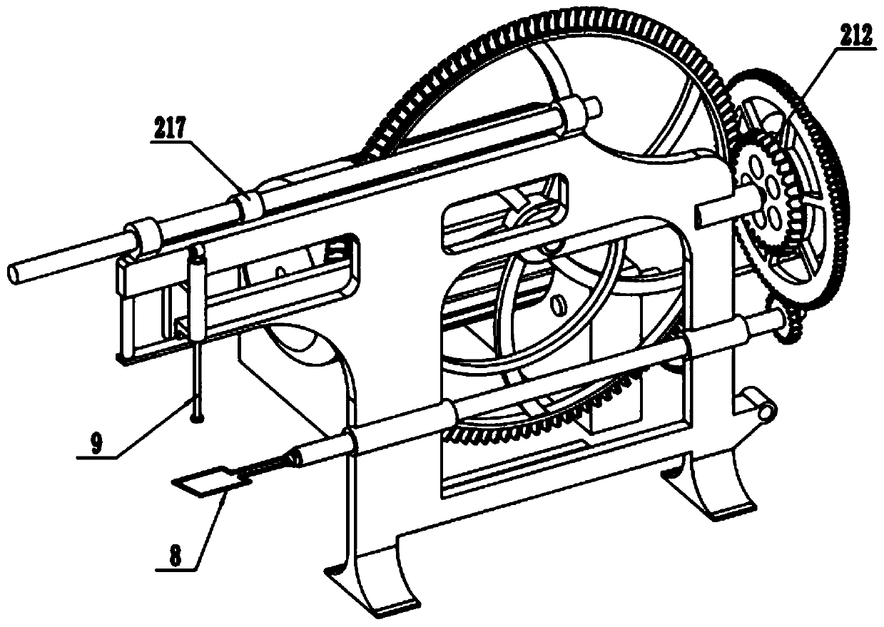
[0017] Such as figure 1 , figure 2 , image 3 , Figure 4 , Figure 5 , Image 6 As shown, an electromagnetic induction phenomenon demonstration device includes a platform 1, a conductor moving mechanism 2, a traveling mechanism 3, a rotating lifting mechanism 4, a placing table 5, a bulb holder 6, a bulb 7, a coil 8, a conductive rod 9, and a wire 10. The conductor moving mechanism 2, the traveling mechanism 3 and the placement platform 5 are all fixedly installed on the platform 1, the traveling mechanism 3 is in front of the conductor moving mechanism 2, the placement platform 5 is on the side of the conductor moving mechanism 2, and the rotating lifting mechanism 4 is fixedly installed on the platform 1. O...


PUM


Abstract

The invention discloses an electromagnetic induction phenomenon demonstration device. The electromagnetic induction phenomenon demonstration device comprises a platform, a conductor moving mechanism,a traveling mechanism, a rotating lifting mechanism, a placing table, bulb seats, bulbs, a coil, a conductive rod, and leads. The conductor moving mechanism, the traveling mechanism and the placing table are fixedly mounted on the platform, the rotating lifting mechanism is fixedly mounted on the traveling mechanism, and the bulb seat is fixedly mounted on the placing table, The bulb is fixedly mounted on the bulb seat, the coil and the conductive rod are respectively fixedly mounted on the conductor moving mechanism, the coil is connected with one of the bulb seats by the lead, and the conductive rod is connected with the other bulb seat by the lead. The device continuously moves the conductor in a magnetic field by the conductor moving mechanism, the magnet includes the conductor throughthe traveling mechanism and the rotating lifting mechanism, and by rotating the magnet to make the conductor in the conductor moving mechanism to performing magnetic line cutting motion and the magnetic line parallel motion, the experimental demonstration effect is more intuitive and easy to understand.

Description

technical field [0001] The invention relates to the technical field of physics teaching experiments, in particular to an electromagnetic induction phenomenon demonstration device. Background technique [0002] Electromagnetic induction is a phenomenon in which a conductor placed in a changing magnetic flux generates an electromotive force. This electromotive force is called induced electromotive force or induced electromotive force. If the conductor is closed into a loop, the electromotive force will drive electrons to flow and form an induced current. The discovery of electromagnetic induction is one of the greatest achievements in the field of electromagnetism. It not only reveals the inner connection between electricity and magnetism, but also lays the experimental foundation for the mutual conversion between electricity and magnetism, and opens up the way for human beings to obtain huge and cheap electric energy. Students who are new to this knowledge point are often di...

Claims


Application Information

Patent Timeline
Patent Type & Authority Patents(China)
IPC IPC(8): G09B23/18
Inventor 汪少斌
Owner 汪少斌
Why Eureka
Try Eureka