System for delivering a stent

a technology for delivering systems and stents, applied in the field of systems for delivering stents, can solve problems such as flexible material collapse on guidewires, and achieve the effect of limiting the proximal movement of stents

Inactive Publication Date: 2007-08-30
BAY STREET MEDICAL
View PDF99 Cites 111 Cited by
  • Summary
  • Abstract
  • Description
  • Claims
  • Application Information

AI Technical Summary

Problems solved by technology

Preferably, advancement of the guidewire and stent causes the flexible material to collapse on the guidewire.

Method used


Image

  • System for delivering a stent
  • System for delivering a stent
  • System for delivering a stent

Examples


Embodiment Construction

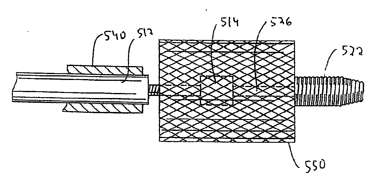
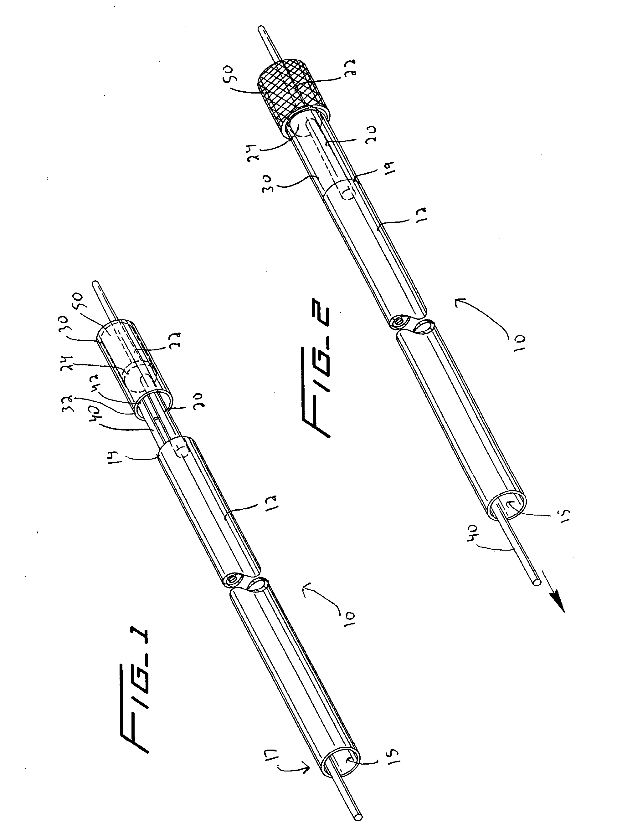
[0061] Referring now in detail to the drawings wherein like reference numerals identify similar or like components throughout the several views, a first embodiment of the stent delivery system of the present invention is shown in FIGS. 1 and 2. In this embodiment, stent delivery system is represented generally by reference numeral 10 and includes a hypotube 12, a tapered core wire (guidewire) 20 extending beyond a distal end of the hypotube 12, a sheath or tube 30 covering the stent, and a control member in the form of a pull wire 40. The guide wire 20 is attached at a proximal end to the distal end region 14 of the hypotube 12 by soldering to the inside wall of the hypotube, by welding or other attachment means. As illustrated, the core wire 20 is located off center from and preferably substantially parallel to a central longitudinal axis of the hypotube 12 and has a smaller diameter than the hypotube. Pull wire 40 extends through lumen 15 in the hypotube 12 so it emerges beyond a ...


PUM


Abstract

A stent delivery system comprising a hypotube having a proximal end portion, a distal end portion and a first diameter, and a guidewire having a second diameter and a reduced diameter portion having a diameter smaller than the first diameter of the hypotube for receiving a stent. The guidewire is slidably positioned within the hypotube. Flexible material, e.g. collapsible tubing such as shrink tubing, extends from a portion of the hypotube to a portion of the guidewire. A stent is positioned on the reduced diameter portion of the guidewire,

Description

[0001] This application claims priority from provisional application No. 60 / 772,660, filed Feb. 13, 2006, the entire contents of which are incorporated herein by reference.BACKGROUND [0002] 1. Technical Field [0003] This application relates to a system for delivering a stent, and more particularly a delivery system wherein a stent is mounted on a hypotube or wire to reduce the overall profile of the system. [0004] 2. Background of Related Art [0005] Intravascular stents are used for treatment of vascular stenosis. One type of stents are balloon expandable stents which are mounted over a balloon. Inflation of the balloon expands the stent within the vessel to dilate the stenosis. Another type of stents is self-expanding, composed of shape memory material. The self-expanding stents are compressed within a sheath and when exposed from the sheath automatically move to an expanded shape memorized position within the vessel. [0006] These stents are delivered to the area of stenosis or an ...

Claims


Application Information

Patent Timeline
Patent Type & Authority Applications(United States)
IPC IPC(8): A61F2/84
CPCA61F2/958A61F2/966A61F2/962
Inventor HEBERT, STEPHENLEVINE, MARC-ALAN
Owner BAY STREET MEDICAL
Why Eureka
Try Eureka