Apparatus for Forming Concrete and Transferring Loads Between Concrete Slabs

a technology of concrete and concrete slabs, applied in the direction of single unit paving, roads, roads, etc., can solve the problems of large pavements that require substantial form preparation and positioning, waste of concrete, and large pavement area for field chamfering, etc., to achieve dependable and effective effect, low cost and high efficiency

Inactive Publication Date: 2007-09-06
CARROLL MICHAEL E
View PDF81 Cites 3 Cited by
  • Summary
  • Abstract
  • Description
  • Claims
  • Application Information

AI Technical Summary

Benefits of technology

[0026] The invention provides improved elements and arrangements thereof, for the purposes described, which are inexpensive, dependable and effective in accomplishing intended purposes of the invention.

Problems solved by technology

Very large pavements require substantial form preparation and positioning.
Regardless of whether the forms are long or short, field chamferring requires considerable time for large pavement areas.
Unfortunately, forms in the field typically have a height that is less than a true height for an appropriate slab thickness.
These forms of inadequate height typically may be positioned so that the top surfaces are at an appropriate height relative to the desired pavement surface height, but present bottom surfaces that do not contact, thus admit gaps through which poured concrete leaks.
This wastes concrete and requires additional work to remove the excess portions.
Concrete leakage from the forms, especially at the butt joints, leaves depressions in a finished slab surface causing poor aesthetics.
The depressions also impair surface coverings, such as tile, because the uneven surface promotes uneven or incomplete covering layout and adhesion.
Cured leaked concrete also impinges on adjacent slabs causing voids and / or increasing the chances of obtaining a locked construction, which leads to cracks and joint failures.
Finally, removing the cured excess typically damages the slab from which the excess is chiseled.
Unfortunately, none of the foregoing provides a method of forming concrete and an apparatus for same that includes stiff, infinitely long, pre-chamferred forms with predetermined true height.
As the concrete of the slab cures, forces derived from the exothermal curing reactions cause generally vertical cracks to develop through the slab thickness at the reduced cross-sections below each groove.
Aggregate interlock causes wear among slab intersections with increasing use of the pavement.
Additionally, cyclical and extreme temperature changes decrease slab volumes.
Thus, over time, as traffic continuously passes over a joint, the intersections wear and become smooth, then fail altogether, resulting in relative vertical displacement of adjacent slab sections, hence a rough pavement surface.
Joint failure also becomes increasingly susceptible to water intrusion, which may freeze and cause damage among adjacent slabs.
Among other problems, the foregoing techniques involve significant time and labor to produce and place the dowels.
Drawbacks of the foregoing include the cost and labor associated with producing separate mounting and load plates, then assembling same following curing of a first concrete slab.
Such restraint of movement in directions other than parallel to the longitudinal axes of dowels 1200 could result in slab failure in the form of cracking.
Unfortunately, none of the foregoing provide a method of forming concrete and an apparatus for same that includes partially coated load plates carried in slotted forms.

Method used


Image

  • Apparatus for Forming Concrete and Transferring Loads Between Concrete Slabs
  • Apparatus for Forming Concrete and Transferring Loads Between Concrete Slabs
  • Apparatus for Forming Concrete and Transferring Loads Between Concrete Slabs

Examples


Embodiment Construction

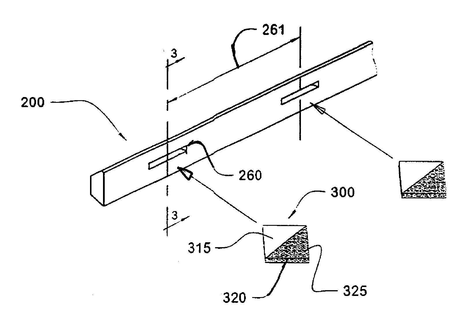
[0047] The invention is a method of forming concrete and an apparatus for same that provide partially coated load plates carried in pre-slotted, stiff, infinitely long, pre-chamferred forms with predetermined true height.

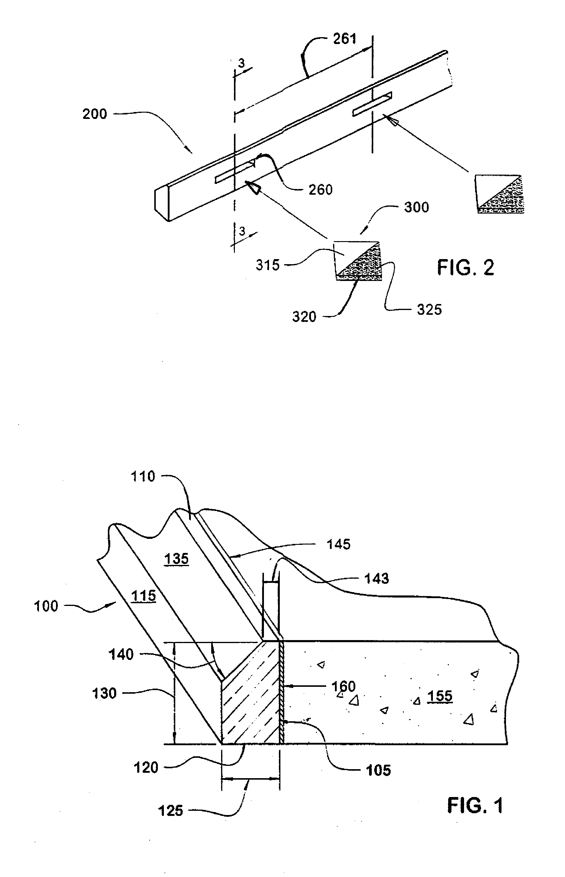
[0048] Referring to FIG. 1, an embodiment of an apparatus for forming concrete configured according to principles of the invention includes a form 100. Form 100 has a side surface 105, a top surface 110, a back surface 115 and a bottom surface 120. Side surface 105 and back surface 115 define a width 125 ranging from 0.875 to 2.500 inches. Top surface 110 and bottom surface 120 define a height 130 ranging from 3 to 18 inches or more, depending on the thickness required for pavement.

[0049] Form 100 has a chamfer 135 between top surface 110 and back surface 115. Chamfer 135 defines an angle 140 relative to top surface 110 ranging from 10° to 89°, preferably 22.5° to 45°. Side surface 105 and chamfer 135 define a top surface width 143 ranging from 0.125 to 0.875 inch...


PUM


Abstract

An embodiment configured according to principles of the invention includes a plate defining a hexagon having a base parallel with joint between concrete slabs. Another embodiment includes a hexagon-shaped plate having a first portion and a second portion, and a form having a slot configured to closely receive the second portion.

Description

REFERENCE TO EARLIER APPLICATIONS [0001] This Application is a divisional patent application of U.S Utility patent application Ser. No. 11109781, which claims the benefit of U.S. Provisional patent application Ser. No. 60 / 650,954, filed Feb. 9, 2005, and is a continuation-in-part of U.S. Utility patent application Ser. No. 11 / 077,557, filed Mar. 11, 2005, by Stephen F. McDonald for Method of Forming Concrete and an Apparatus for Same.BACKGROUND OF THE INVENTION [0002] Conventional concrete pavement installation involves preparing then positioning forms around an area intended for pavement. The forms have vertical inner surfaces to receive and contain poured concrete. The forms have horizontal top surfaces, which typically are level with the surface of the poured concrete, or, once cured, pavement surface. The forms have back surfaces that rest against appropriately-spaced stakes for holding the forms in place. To provide clearance for finish troweling, concrete workers often field c...

Claims


Application Information

Patent Timeline
Patent Type & Authority Applications(United States)
IPC IPC(8): E04F21/00E01C11/14E04C3/30E04F15/14E04G11/36
CPCE01C11/14E04G11/365E04F15/14E04G11/36E01C5/06E01C2201/12E04C3/30E01C11/02
Inventor CARROLL, MICHAEL E.
Owner CARROLL MICHAEL E
Why Eureka
Try Eureka