
Method of Denitrifying Wastewater

Active Publication Date: 2009-09-24
HOOT AEROBIC SYST
View PDF18 Cites 0 Cited by
  • Summary
  • Abstract
  • Description
  • Claims
  • Application Information

AI Technical Summary

Benefits of technology

[0044]The invention overcomes the disadvantages noted above by providing apparatus for and method of denitrifying a solution that employs an inexpensive, non-toxic, unregulated carbon source that promotes activity of heterotrophic bacteria that reduce all nitrate (NO3<sup2>−< / sup2>) in solution.
[0050]The invention provides improved elements and arrangements thereof, for the purposes described, which are inexpensive, dependable and effective in accomplishing intended purposes of the invention.

Problems solved by technology

Refractory Nitrogen cannot be decomposed biologically.
Nitrite (NO2−) is unstable and is easily converted into nitrate.
An effluent with high nitrite (NO2−) concentrations is difficult to disinfect because of the tremendous chlorine demand it poses.
Other problems also can occur during nitrification.
A decrease in the aeration tank pH due to insufficient alkalinity causes ammonia (NH3) to bleed through the system, which causes decreased microbiological activity.
High nitrite (NO2−) levels will cause a tremendous chlorine demand making disinfection difficult, jeopardizing fecal coliform limits.
Leaving sludge that is high in nitrate (NO3−) too long in a secondary clarifier can cause it to rise to the surface when the nitrogen gas is released.
This is messy and jeopardizes TSS limits.
Aside from permit limits, ammonia (NH3) is toxic to fish and other aquatic life.
Second, a carbon source must exist for denitrification to occur.
However, these compounds leave much to be desired for use as denitrification carbon sources for wastewater treatment units, especially on-site wastewater treatment units.
When diluted to safer levels, it becomes very bulky.
Acetate salts also are hazardous solids, and face the same fate on adequate dilution.
These solutions are bulky, and leave solid residue on drying that can foul the equipment.
The residual from utilization by the bacteria is an increase in alkalinity that is impractical to control in an unattended system.
These alcohols also have their own limitations with respect to on-site use.
These traditional supplementary carbon sources, methanol and ethanol, have undesirable characteristics, especially for on-site use, including acute toxicity; volatile; flammable; and form explosive vapor mixtures with air in confined spaces.
Ethanol, while grain derived in its natural form is highly regulated and expensive.
These approaches do not completely denitrify the wastewater so treated.

Method used


Image

  • Method of Denitrifying Wastewater
  • Method of Denitrifying Wastewater
  • Method of Denitrifying Wastewater

Examples


Embodiment Construction

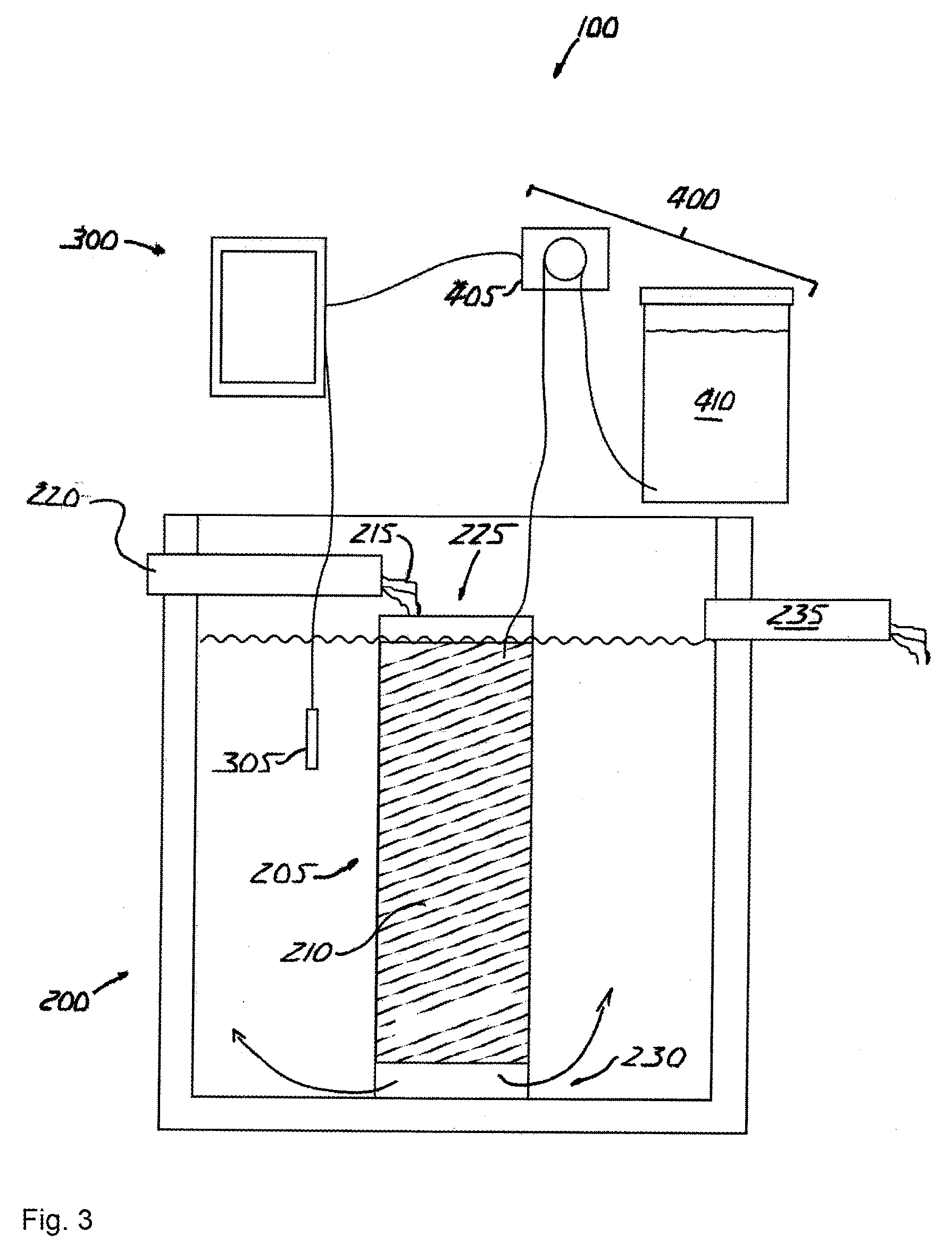
[0057]The invention is an apparatus for and method of denitrifying a solution that accepts nitrified solution and introduces a carbon source into the solution that promotes heterotrophic bacterial reduction of nitrate (NO3−).

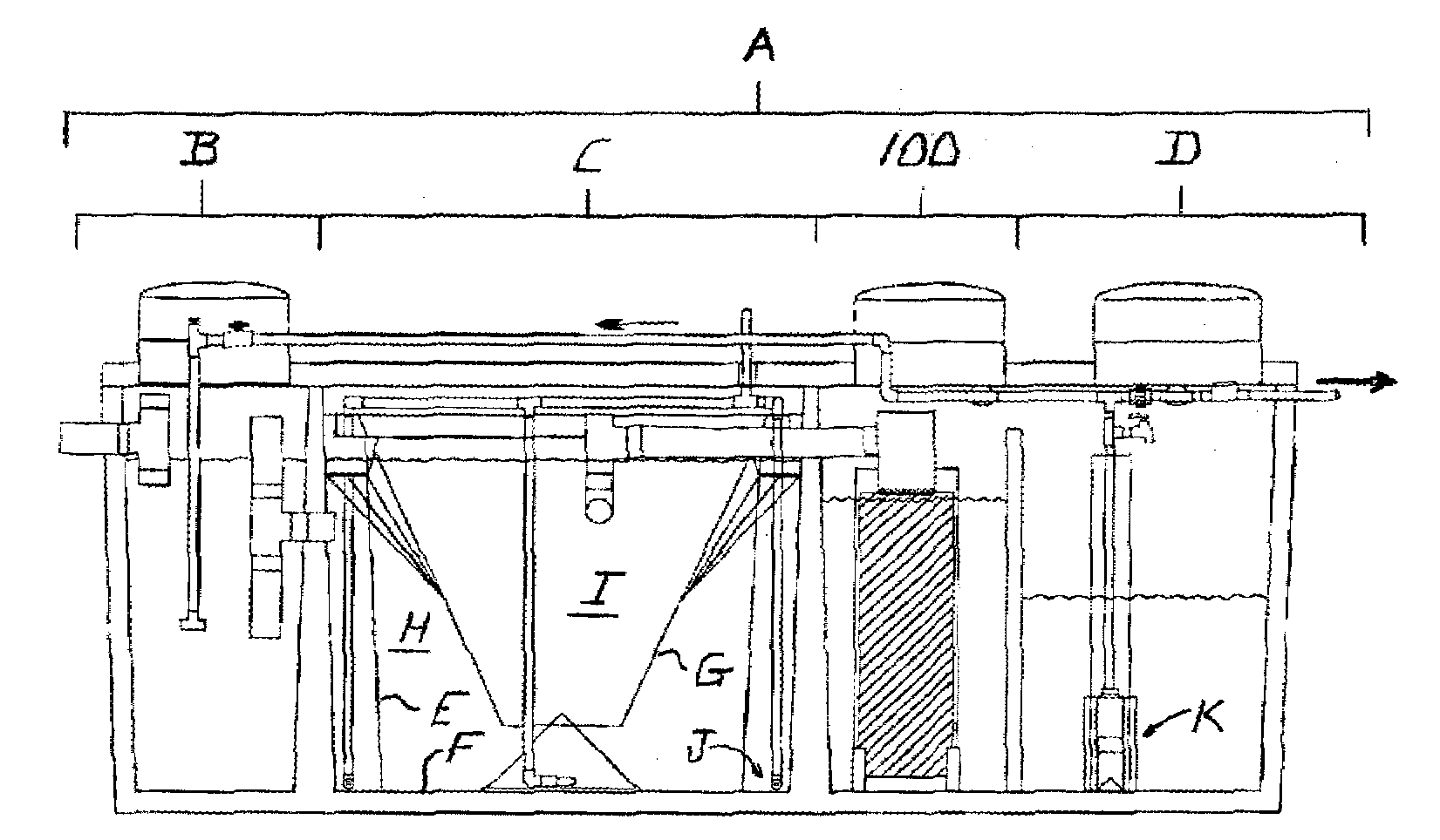
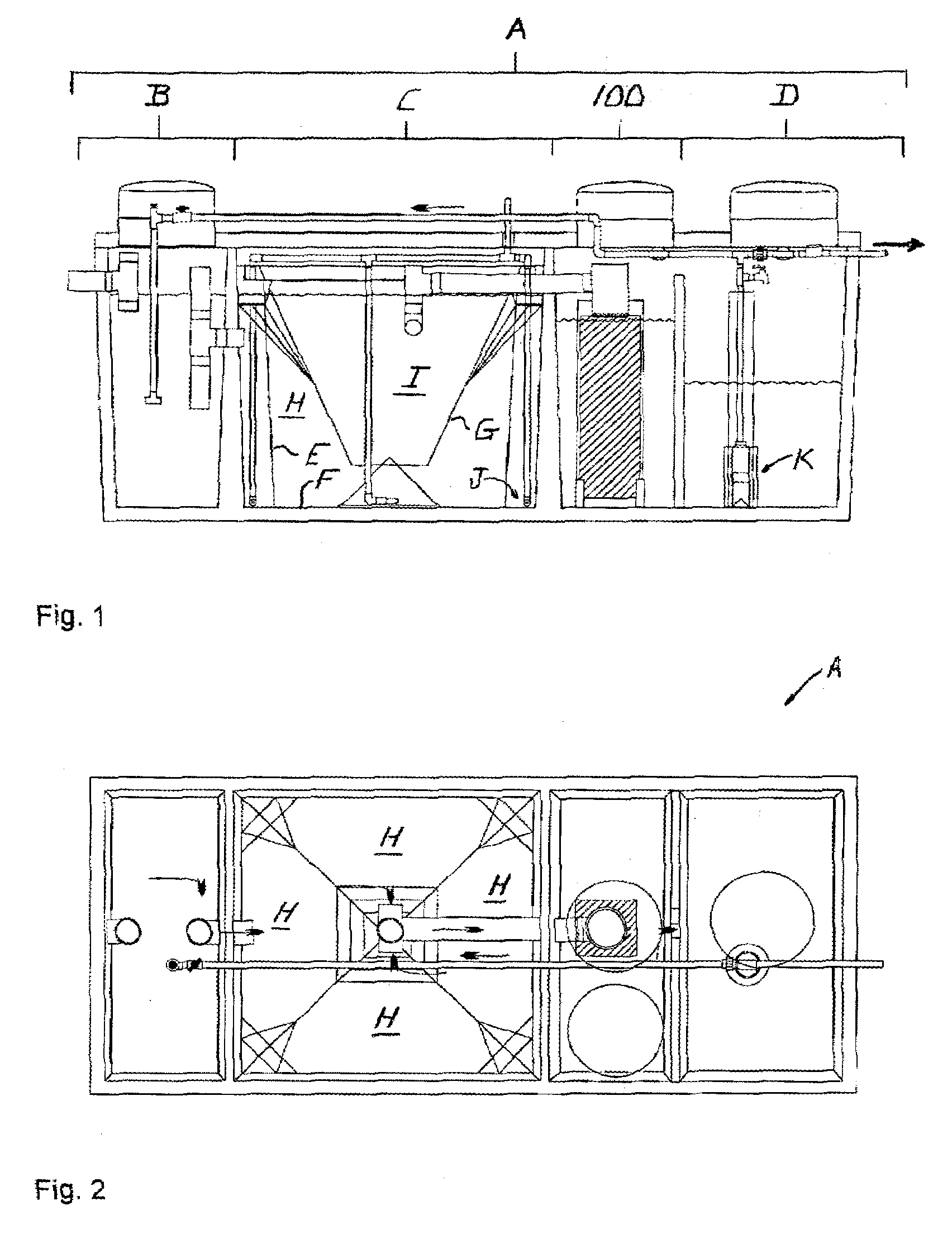
[0058]Referring to FIGS. 1 and 2, a denitrification apparatus 100 is shown incorporated in a conventional wastewater treatment plant A. Wastewater treatment plant A includes a pre-treatment tank B, a treatment tank C and a holding tank D. Untreated solution flows into the pre-treatment tank B, into and through the treatment tank C, into and through denitrification apparatus 100, into and through the holding tank D, then is voided into the environment.

[0059]Pre-treatment tank B receives raw, untreated wastewater and initiates the aerobic phase of treatment during which aerobic bacteria break down the wastewater. Pre-treatment tank B also retains any non-biodegradables inadvertently introduced into the system, such as rags and plastic, which settle out prior to in...


PUM


Abstract

Disclosed is a method of denitrifying a solution including introducing into the solution an amount of a carbon source within a duration and at a frequency so that indigenous heterotrophic bacteria deplete dissolved oxygen in the solution and obtain oxygen from nitrate in the solution. Related apparatuses and compounds also are disclosed.

Description

REFERENCE TO EARLIER APPLICATIONS[0001]This application claims is a divisional of priority to and incorporates by reference U.S. patent application Ser. No. 11 / 722,010, filed Jun. 18, 2007, which incorporates by reference and is a National Phase of International Patent Application No. PCT / US07 / 68288, filed May 4, 2007.BACKGROUND OF THE INVENTION[0002]Denitrification of solutions is useful for many reasons, such as limiting the total nitrogen discharged in wastewater to comply with local permits. Other reasons include: improving freshwater quality; controlling alkalinity and oxygen recovery, producing stabilized effluent, and reducing issues stemming from sludge accumulation in the clarifier.[0003]Removing nitrogen from wastewater requires understanding the different forms of nitrogen and some commonly referred to terms:[0004]Total Nitrogen (TN) is the sum of all nitrogen forms or:Total Nitrogen=TKN+NO2<sup2>−< / sup2>+NO3<sup2>−< / sup2>where:[0005]TKN stands for...

Claims


Application Information

Patent Timeline
IPC IPC(8): C02F3/30C02F1/70
CPCC02F3/006C02F3/1247C02F3/2806C02F3/302C02F2209/04C02F2209/40C02F2209/06C02F2209/07C02F2209/15C02F2209/22C02F2209/05Y02W10/10Y02A20/208
Inventor CORMIER, MURPHY J.SUCHECKI, JR., RONALD J.PERTUIT, ROBERT K.BROWN, DONALD L.CORMIER, TROY L.
Owner HOOT AEROBIC SYST
Learn More