
Automated reactor endpointing of platy interference effect pigments

a technology of interference effect and reactor endpoint, which is applied in the direction of optical radiation measurement, instruments, spectrophotometry/monochromators, etc., can solve the problems of inability to use known methods in connection with pearlescent production, and inability to achieve color-matched pigment output. , to achieve the effect of reducing in-process testing times, reducing inter-batch variability, and increasing color-matched pigment outpu

Inactive Publication Date: 2006-02-14
ENGELHARD CORP
View PDF16 Cites 0 Cited by
  • Summary
  • Abstract
  • Description
  • Claims
  • Application Information

AI Technical Summary

Benefits of technology

[0011]The invention provides for significantly increasing color-matched pigment output by reducing in-process testing times. The invention provides for reducing inter-batch variability by removing subjective evaluation. The invention provides for reducing lost time and money occasioned by poor product quality. The invention provides for maintaining color consistency, especially with respect to colors of differing intensities and the presence of free coating particles, which make traditional methods of color matching difficult due to interference or subjectivity. The invention provides for matching colors of interference pigments which change rapidly due to high reaction rates, which otherwise would be easy to miss. The invention provides improved elements and arrangements thereof, for the purposes described, which are inexpensive, dependable and effective in accomplishing intended purposes of the invention.

Problems solved by technology

This method is imprecise and susceptible to unpredictable or untimely production.
The known methods are inappropriate for use in connection with production of pearlescent or “effect” interference pigments.
Depending on the thickness of the metal oxide layer, they can also exhibit interference color effects.
Control of the product characteristics is complicated by the fact that free particles of the coating, unattached to a platy substrate, can form and effect the apparent color and also because the color changes rapidly as a result of high reaction rates.
This is clearly not optimal.
This also is clearly impractical and time consuming.

Method used


Image

  • Automated reactor endpointing of platy interference effect pigments
  • Automated reactor endpointing of platy interference effect pigments
  • Automated reactor endpointing of platy interference effect pigments

Examples


example 1

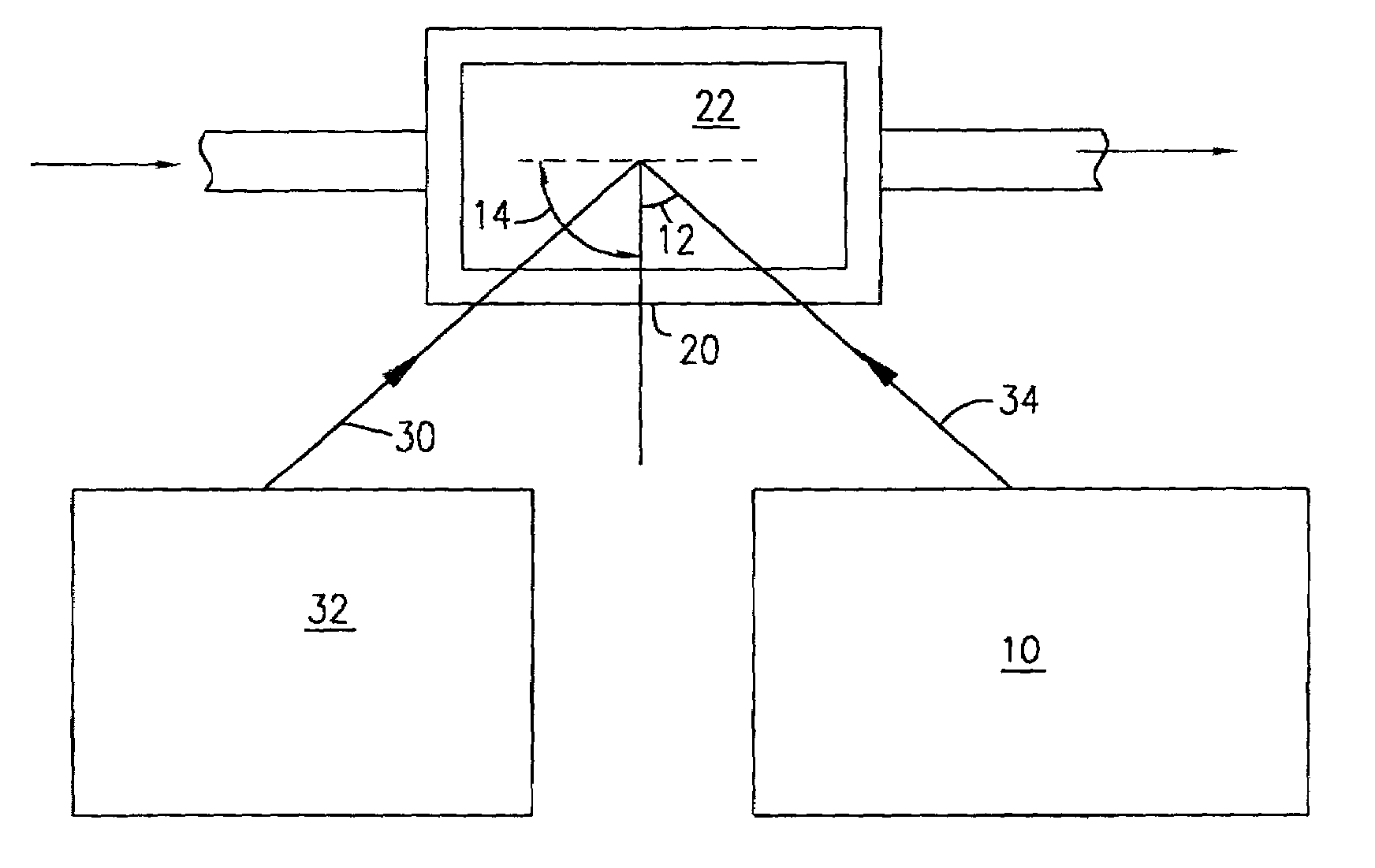
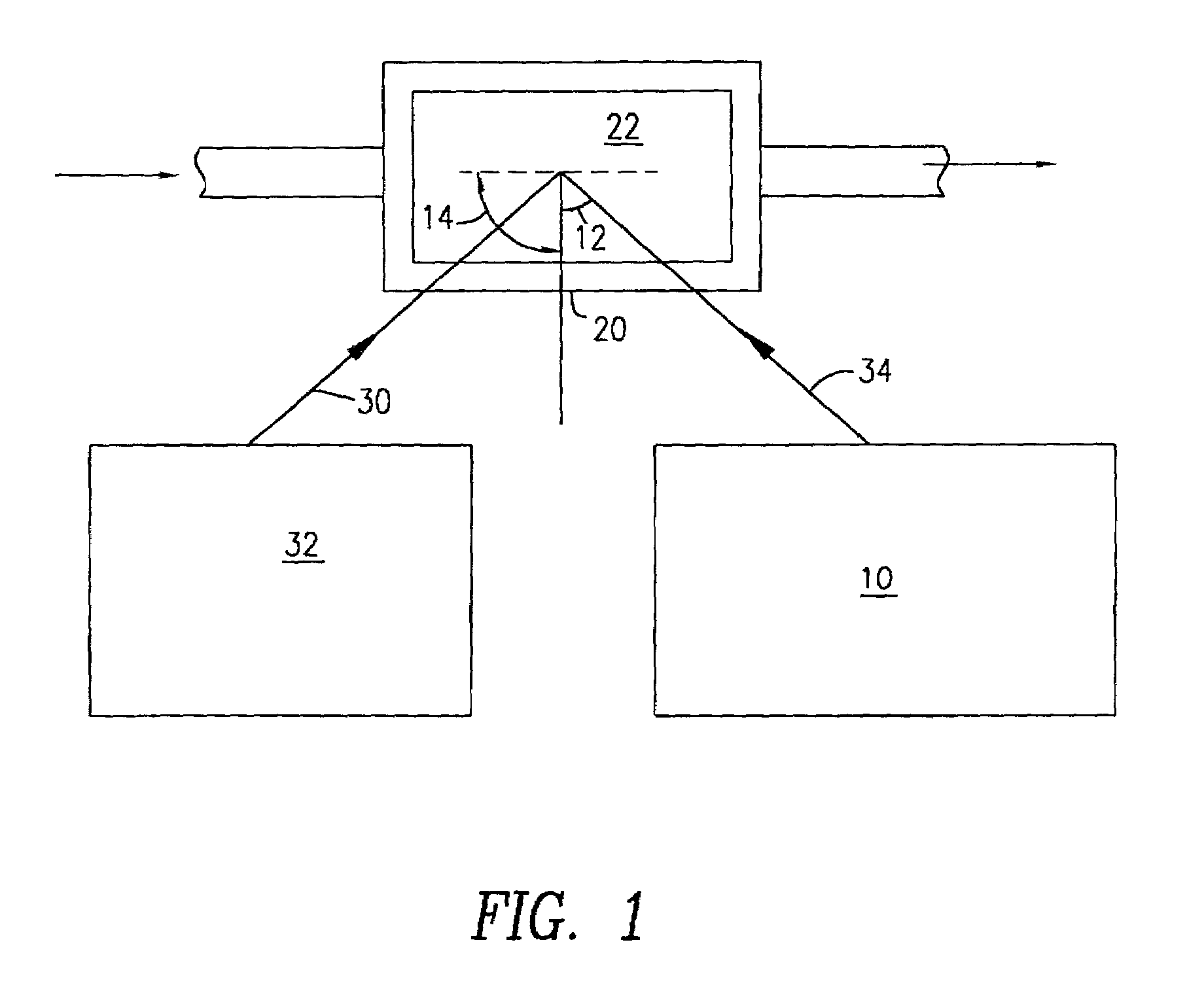
[0027]A slurry of glass platelets in a morton flask was titrated with a solution of TiOCl2 and NaOH such that a hydrated TiO2 layer formed on the borosilicate platelets which generated an interference color. As the film developed, the slurry periodically was pumped through a flow cell, measuring 5×5.5×0.1 cm, with a peristaltic pump at approximately 200 ml / min.

[0028]The flow cell was mounted on a goniospectrophotometer. The goniospectrophotometer measured the color of light reflected off of a first target slurry to determine the desired endpoint color. Measurements were taken at 25 degrees from the specular angle.

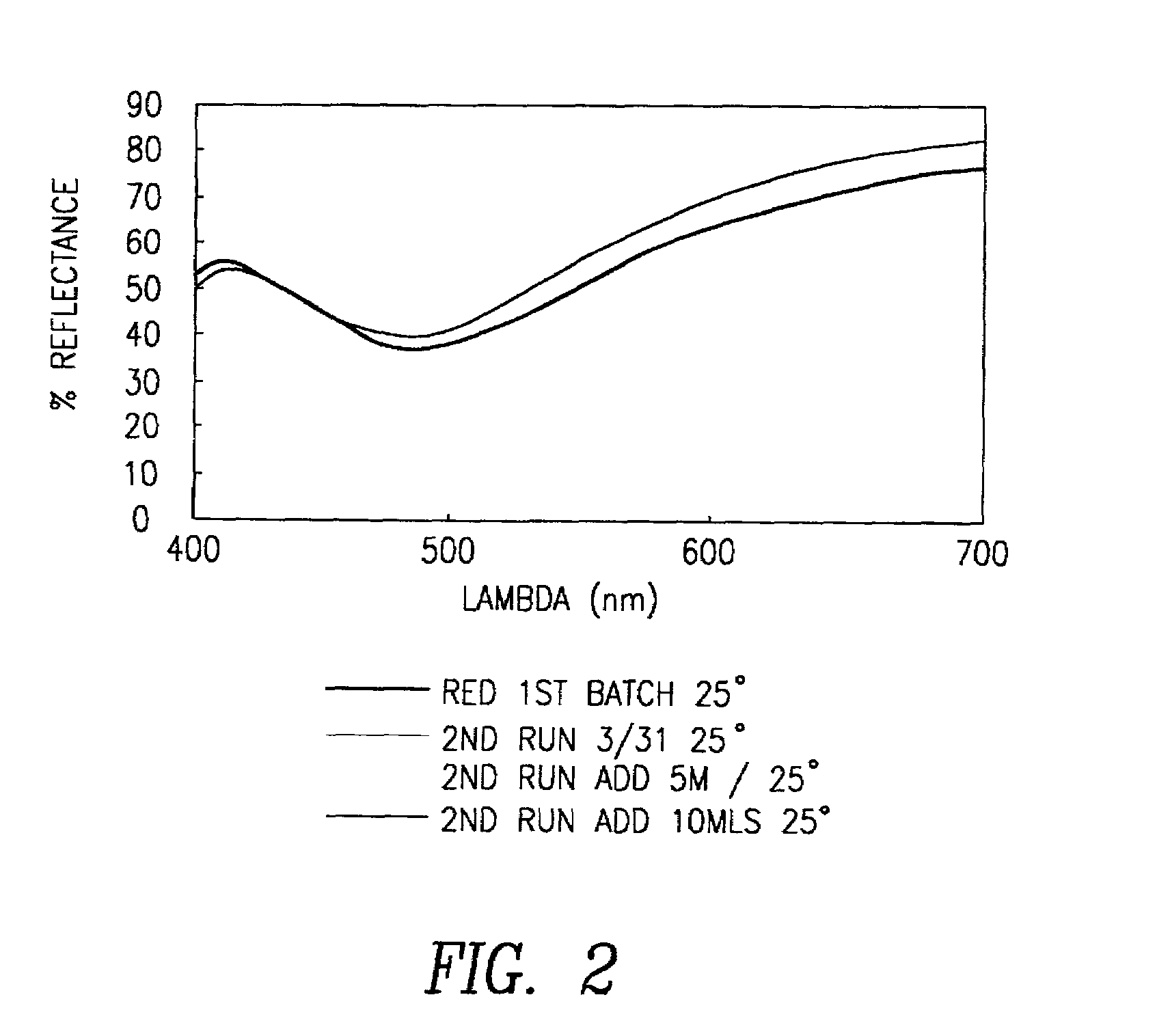
[0029]The goniospectrophotometer measured the color of samples during a second coating run at different stages of the coating process. A color match was established for each sample based on Lmin. FIG. 2 shows the spectra of the slurries measured with the flow cell. When the first and second slurry colors matched, the coating process was stopped, and the sample was washed, f...

example 2

[0030]The slurry of this example was similar to that in example 1, except that the slurry included mica coated with hydrated TiO2. First, a red TiO2 coated mica effect pigment was measured and established as the standard. Additional samples were evaluated during the coating of a second mica batch. Color data generated from the flow cell system indicated completion of the reaction. The samples were processed further to produce a good color match.


PUM


Abstract

An apparatus and a method for objectively ascertaining a color match between a selected standard color and the color exhibited by an interference effect pigment during processing thereof and terminating the process upon achieving a match. The invention provides a spectrophotometer attached to a flow cell to monitor the color of a platy effect pigment to monitor pigment color and ascertain completion of the coating reaction process involved in interference pigment production.

Description

BACKGROUND OF THE INVENTION[0001]Producers of colored products and dispersions seek to achieve a consistent color of their products using many techniques. One simple method involves halting a pigmentation process, applying a coat of the material to a surface and comparing the dried coat to a standard. This method is imprecise and susceptible to unpredictable or untimely production.[0002]Other methods involve evaluating a liquid during the pigmentation process. For example, one method includes directing a portion of a dispersion through a flow cell. One technique provides for observing an illuminated dispersion flowing through the flow cell for comparison with a standard. Another technique directs light through the dispersion in the flow cell onto a spectrometer which compares the characteristics of the light received with specified characteristics.[0003]The known methods are inappropriate for use in connection with production of pearlescent or “effect” interference pigments. Such pi...

Claims


Application Information

Patent Timeline
IPC IPC(8): G01J3/42G01J3/50G01J3/46G01N21/05G01N21/25G01N21/27G01N21/45
CPCG01J3/50G01J3/504G01N21/85G01N21/251G01N21/05G01J3/463G01N21/45G01N2021/0346G01J3/46
Inventor CARROLL, JR., JAMES B.WILLARD, CHARLES
Owner ENGELHARD CORP
Learn More