Encoder signal analysis system for high-resolution position measurement

a signal analysis and encoder technology, applied in the direction of automatic disconnection emergency protection arrangements, speed/acceleration/shock measurement devices, etc., can solve the problems of inability to compensate, unpredictable or unpredicted variations cannot be anticipated, and the use of such “mapped” signal deviations by the interpolator is limited

Inactive Publication Date: 2007-09-06
MOOG INC
View PDF2 Cites 22 Cited by
  • Summary
  • Abstract
  • Description
  • Claims
  • Application Information

AI Technical Summary

Benefits of technology

The patent describes a method for creating a set of sensor signals that can be used to determine the position of an object. The method involves using an array of sensors that are placed in a specific pattern. Each sensor in the array is designed to sense a periodic field that is shifted in phase by 180 degrees with another sensor in the array. By combining the signals from each sensor in the array, the method compensates for any slow variations in the field that might occur. The technical effect of this method is to create a more accurate and reliable way to measure position.

Problems solved by technology

The technical problem addressed in this patent text is the inability of prior art interpolators to compens for uncertained variations in sensor signals, such as changes in magnetic field or temperature, which can result in position output signal errors. The patent text proposes an improved interpolator that can provide a highly linear output position signal in the presence of substantial sensor signal distortion.

Method used


Image

  • Encoder signal analysis system for high-resolution position measurement
  • Encoder signal analysis system for high-resolution position measurement
  • Encoder signal analysis system for high-resolution position measurement

Examples


Embodiment Construction

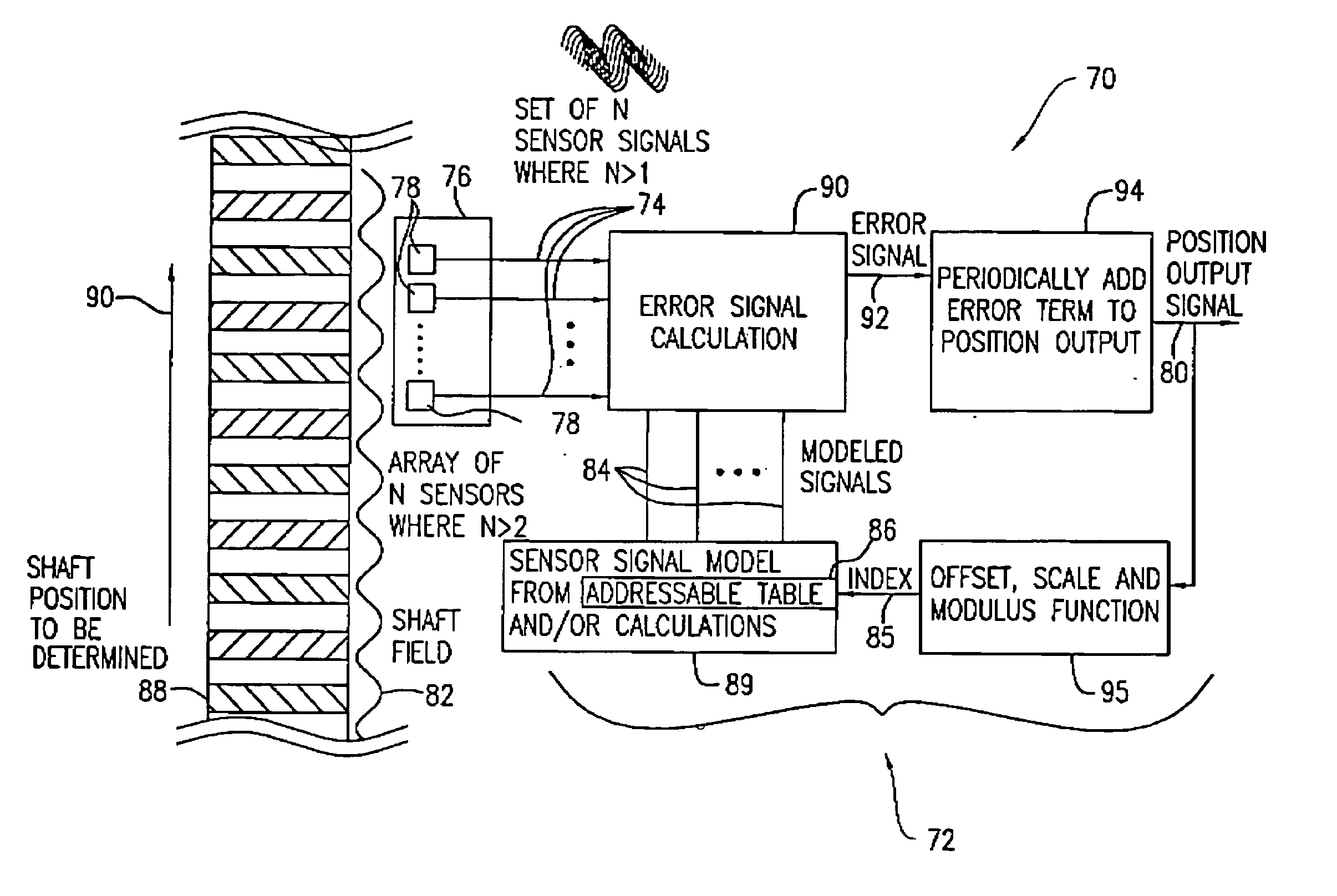
[0109] Returning to FIG. 6, the invention provides a method and apparatus 70 for statistical interpolation of sensor signal data in such a manner as to provide improved linearity over prior art interpolators. The apparatus 70 includes a statistical interpolator 72 that interpolates the output signals 74 of a sensor array 76 consisting of N sensors 78, where N is greater than 2, wherein the sensors are placed so that their outputs 74 are shifted in phase preferably by 180 / N degrees, or a multiple thereof, and outputs a signal 80 representing the position of the sensors 78 relative to a periodic sensed field 82. The statistical interpolator and method of identifying a position by statistical interpolation of the present invention are preferably implemented in a digital signal processor, but can be any combination of software instructions in a programmable processor or processors and hardware for implementing the methods described herein.

[0110] An appropriate number N of sensors 78 ar...


PUM


Abstract

An apparatus and method for identifying the position of a magnetic shaft are provided. N field sensors are adjacently positioned at fixed locations relative to the shaft's periodic field, corresponding to 180/N relative phase shifts. A table provides N>2 predetermined signal models and a pre-identified position associated with each. An interpolator compares a representation of the N measured sensor signals to at least two predetermined models to generate a correction signal that provides another pre-identified position. The correction signal depends on N sensors for every position of the shaft. The correction signal is used to incrementally choose said another pre-identified position from the table as an approximate position of the shaft in an iterative process to find the minimum correction signal and identify the position.

Description


Claims


Application Information

Patent Timeline
Owner MOOG INC
Why Eureka
Try Eureka