
Apparatus and method for processing 3D video signal

a technology of video signal and apparatus, applied in the field of processing a three-dimensional (3d) video signal, can solve the problems of inability to provide stereoscopic videos to users, inability to establish binocular fusion, and eye strain

Inactive Publication Date: 2007-05-31
SAMSUNG ELECTRONICS CO LTD
View PDF3 Cites 36 Cited by
  • Summary
  • Abstract
  • Description
  • Claims
  • Application Information

AI Technical Summary

Benefits of technology

The present invention provides an apparatus and method for processing a 3D video signal that corrects differences between first and second video signals to prevent a reduction in 3D effect and disparity estimation errors. The video signals can be adjusted based on the characteristics of the signals, such as contrast, color, brightness, and geometric distortion. The apparatus can also allow users to adjust the correction levels to provide an optimal 3D effect for their needs. Additionally, the invention provides a video signal evaluation unit to determine the degree of fatigue between the video signals and make a determination on whether to correct the signals based on the comparison result. The correction levels can be provided to users in the form of an on-screen display or an on-screen graphic.

Problems solved by technology

However, when a difference between first and second video signals exceeds a predetermined threshold, binocular fusion is not established.
Therefore, stereoscopic videos cannot be provided to users, and eyestrain is caused.
In addition, when eyestrain is reduced by correcting a disparity between objects within a video and correcting the perception of depth of the objects, a disparity estimation error may occur due to the difference between the first and second video signals.
In other words, when a block-based disparity estimation method is used to estimate the disparity between the first and second video signals to correct the disparity therebetween, an estimation error occurs in the process of estimating the disparity between the first and second video signals in a part adjacent to an edge of an image of the video.
However, when there is, for example, a brightness difference between the first and second video signals, an error occurs when the block most similar to each of the blocks in the first image is estimated in the second image.

Method used


Image

  • Apparatus and method for processing 3D video signal
  • Apparatus and method for processing 3D video signal
  • Apparatus and method for processing 3D video signal

Examples


Embodiment Construction

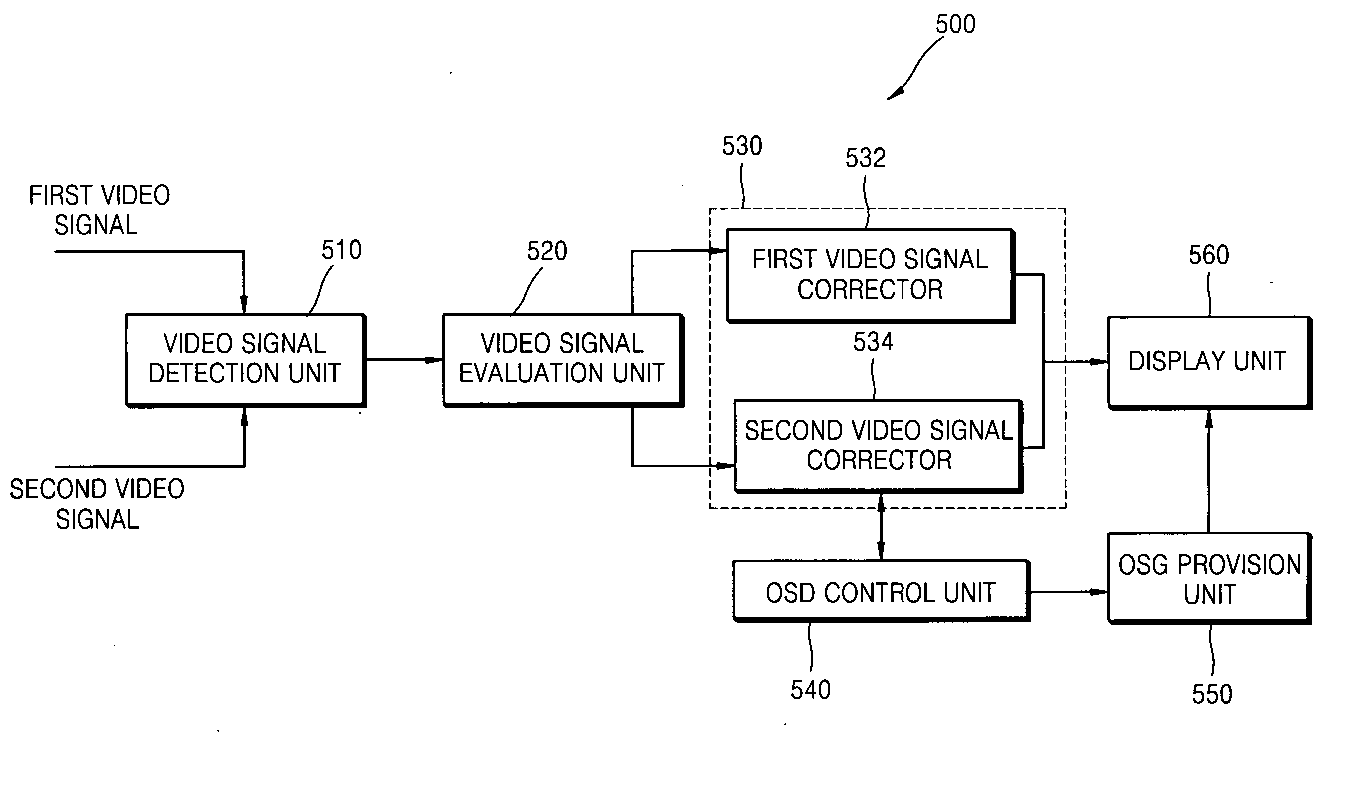
[0042] The present invention will now be described more fully with reference to the accompanying drawings, in which exemplary embodiments of the invention are shown. The invention may, however, be embodied in many different forms and should not be construed as being limited to the embodiments set forth therein; rather, these embodiments are provided so that this disclosure will be thorough and complete, and will fully convey the concept of the invention to those skilled in the art.

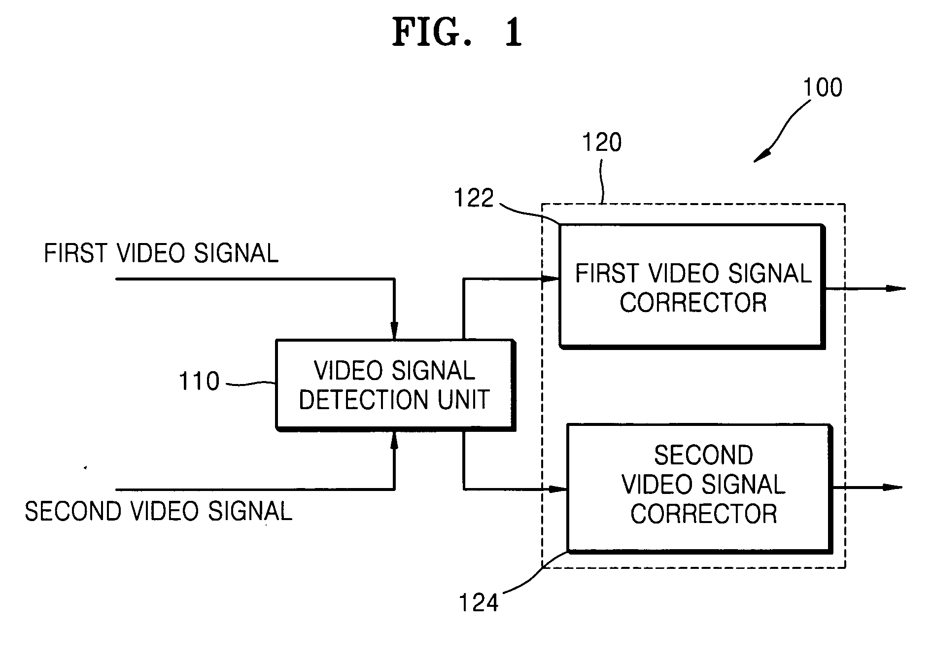
[0043]FIG. 1 is a block diagram of an apparatus 100 for processing a three-dimensional (3D) video signal according to an embodiment of the present invention.

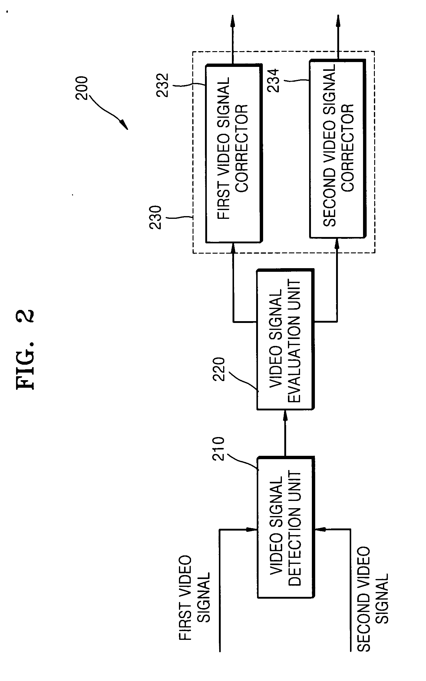
[0044] Referring to FIG. 1, the apparatus 100 includes a video signal detection unit 110 and a video signal correction unit 120. The apparatus 100 receives a first video signal and a second video signal and corrects the first and second video signals to equalize respective characteristics thereof. In an exemplary case, the characteristics of the firs...


PUM


Abstract

Provided are an apparatus and method for processing a three-dimensional (3D) video signal which corrects first and second video signals to prevent a reduction in a 3D effect and a disparity estimation error due to a difference between the first and second video signals. The method includes: a video signal detection unit detecting a difference between respective characteristics of received first and second video signals; and a video signal correction unit correcting the first video signal or the second video signal to equalize the characteristics of the first and second video signals. When the apparatus and the method are used, a reduction in the 3D effect and the disparity estimation error due to the difference between the first and second video signals can be prevented.

Description

BACKGROUND OF THE INVENTION [0001] This application claims the priority of Korean Patent Application No. 10-2005-0114369, filed on Nov. 28, 2005, in the Korean Intellectual Property Office, the disclosure of which is incorporated herein in its entirety by reference. [0002] 1. Field of the Invention [0003] Apparatuses and methods consistent with the present invention relate to processing a three-dimensional (3D) video signal, and more particularly, to processing a 3D video signal in a manner that corrects first and second video signals to prevent a reduction in a 3D effect and a disparity estimation error due to a difference between the first and second video signals. [0004] 2. Description of the Related Art [0005] Most 3D videos and 3D display devices utilize a binocular disparity. To obtain a real video, a stereo camera having two incident lenses is used. In the case of 3D computer graphics (CG), two or more virtual cameras are used to obtain videos in the same way that a real vide...

Claims


Application Information

Patent Timeline
Patent Type & Authority Applications(United States)
IPC IPC(8): H04N13/04H04N23/40G09G3/20G09G5/36
CPCH04N13/0025H04N13/0033H04N2213/002H04N13/144H04N13/133
Inventor KIM, TAE-HEEYU, PIL-HOKIM, DAE-SIK
Owner SAMSUNG ELECTRONICS CO LTD
Learn More