
Image stabilization control apparatus and imaging apparatus

a control apparatus and image stabilization technology, applied in the field of image stabilization control apparatus and imaging apparatus, can solve the problems of small image degradation, large image degradation, and the output signal of the acceleration meter used in detecting parallel vibration, and achieve high operability and high accuracy

Active Publication Date: 2010-01-21
CANON KK
View PDF6 Cites 36 Cited by
  • Summary
  • Abstract
  • Description
  • Claims
  • Application Information

AI Technical Summary

Benefits of technology

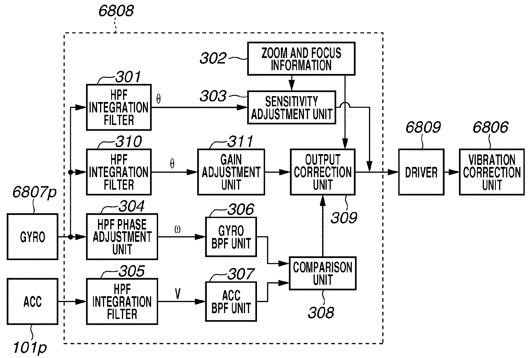
The present invention is about a small-sized image stabilization control apparatus that can correct image shake caused by vibration. It includes a vibration correction unit, two vibration detection units, two extractors, and an output correction unit. The vibration detection units detect the angular velocity and acceleration of vibration, and the extractors extract signals in specific frequency bands. The output correction unit corrects the output of the first vibration detection unit based on the signal from the second extractor. The driving unit then drives the vibration correction unit based on the corrected output. The technical effect of this invention is that it provides a high-operability and accurate solution for correcting image shake caused by parallel vibration.

Problems solved by technology

Meanwhile, when an image is taken at a close distance (under a shooting condition in which a high imaging magnification is used), a significant image degradation due to parallel vibration, which may otherwise cause little image degradation, may occur in addition to angular vibration, which may occur due to the orientation of the camera.
In this regard, however, in the method discussed in Japanese Patent Application Laid-Open No. 07-225405, an output signal from the acceleration meter, which is used in detecting parallel vibration, may vary due to disturbance noises or environmental variation such as temperature change.
Accordingly, it is difficult to highly accurately correct parallel vibration with this method.
Furthermore, in the method discussed in Japanese Patent Application Laid-Open No. 2002-359769, it takes a long time before setting an optimum vibration characteristic.
Accordingly, the user operability of the camera may degrade.
In addition, a large size mechanism of the vibration correction unit may become necessary to implement vibration correction using a variable vibration correction amount.

Method used


Image

  • Image stabilization control apparatus and imaging apparatus
  • Image stabilization control apparatus and imaging apparatus
  • Image stabilization control apparatus and imaging apparatus

Examples


Embodiment Construction

[0085]Various exemplary embodiments, features, and aspects of the present invention are described in detail below with reference to the drawings. The relative arrangement of the components, the numerical expressions, and numerical values set forth in these embodiments are not intended to limit the scope of the present invention.

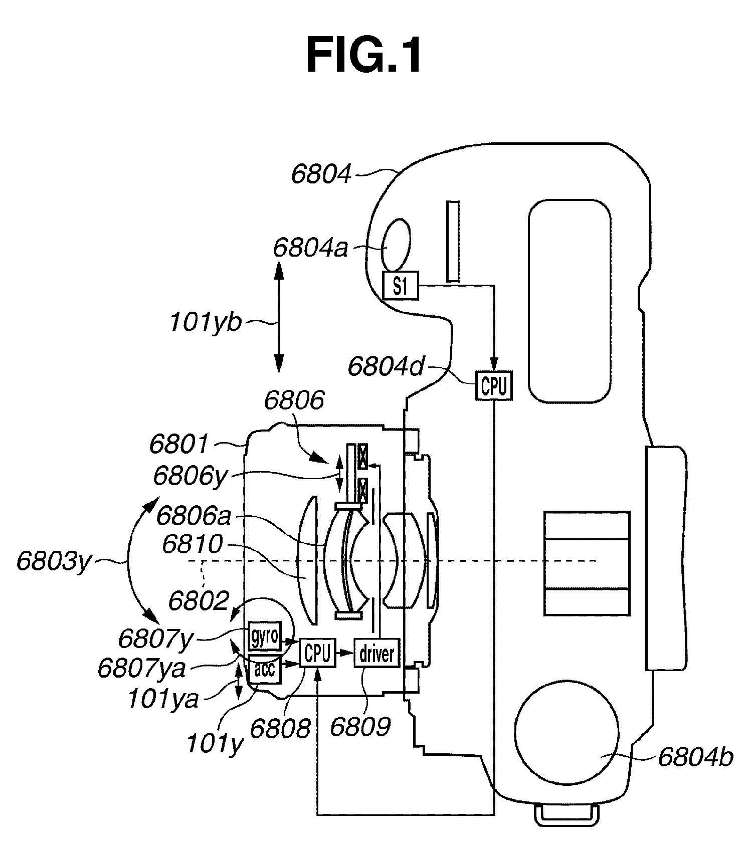
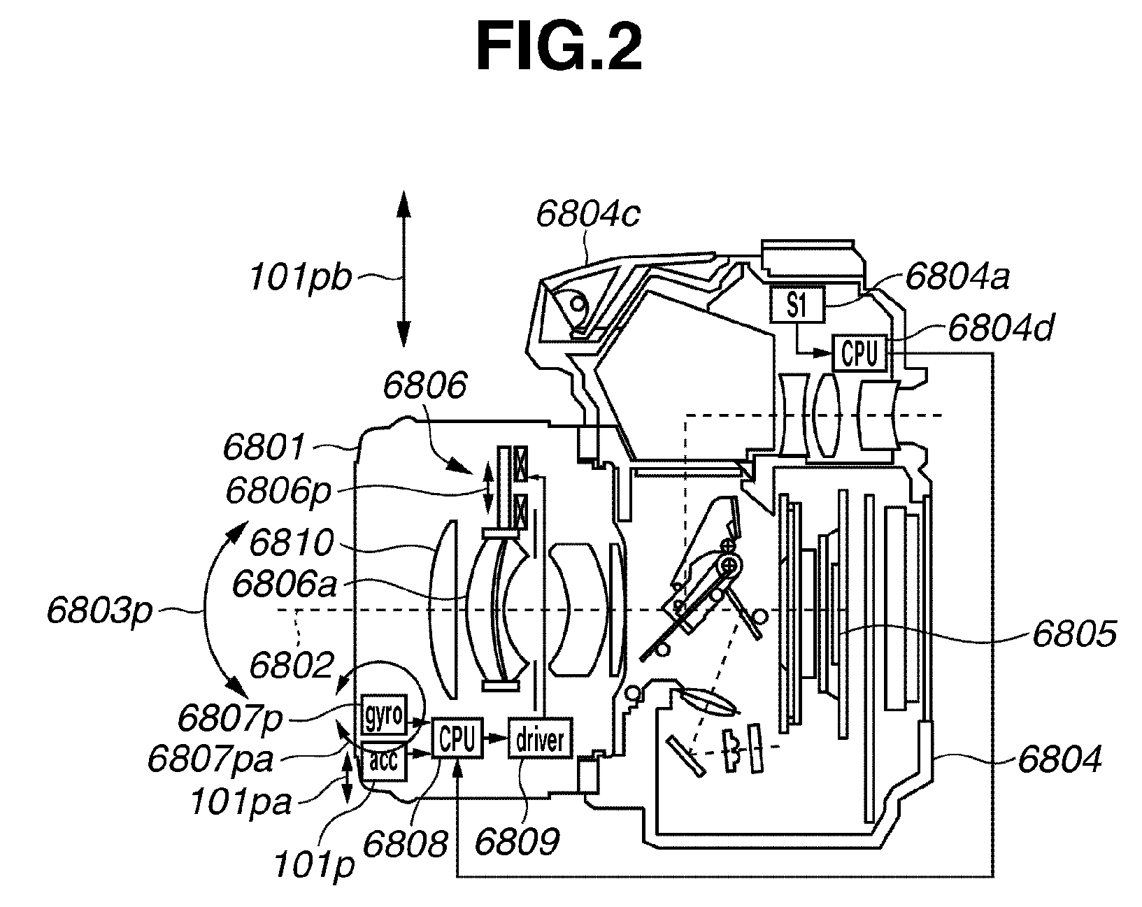
[0086]A first exemplary embodiment of the present invention is described below. FIGS. 1 and 2 are a plan view and a side view illustrating an example of a single-lens reflex camera having an image stabilization control apparatus according to the present exemplary embodiment.

[0087]Referring to FIG. 1, an exchangeable photographic lens 6801 having a vibration correction unit is mounted on a camera body 6804. The vibration correction unit is described in detail below. To briefly describe the vibration correction unit, the vibration correction unit executes correction of image shake such as vibration occurring in a vertical or horizontal direction of an optical a...


PUM


Abstract

An image stabilization control apparatus includes a vibration correction unit configured to correct an image shake occurring due to vibration, a first vibration detection unit configured to detect and output an angular velocity of the vibration, a second vibration detection unit configured to detect and output an acceleration of the vibration, a first extractor configured to extract a signal in a predetermined frequency band based on an output of the first vibration detection unit, a second extractor configured to extract a signal in a predetermined frequency band based on an output of the second vibration detection unit, an output correction unit configured to correct the output of the first vibration detection unit based on the signals extracted by the first and second extractors, and a driving unit configured to drive the vibration correction unit based on the output of the first vibration detection unit as corrected.

Description

BACKGROUND OF THE INVENTION[0001]1. Field of the Invention[0002]The present invention relates to an image stabilization control apparatus and an imaging apparatus configured to correct or prevent an image shake or image degradation occurring due to vibration such as hand shake.[0003]2. Description of the Related Art[0004]In recent years, all operations of a camera significant to shooting, such as an operation for determining the exposure and a focusing operation, may be automatically performed. Accordingly, even a user who is not accustomed to using a camera may very rarely fail in photographing.[0005]In addition, a recently marketed camera includes an image stabilization control apparatus, which includes a vibration correction unit, a driving unit, and a vibration detection unit and is configured to prevent an image shake occurring due to vibration. By using such a recent camera, a photographer may rarely fail in photographing.[0006]An image stabilization control apparatus configur...

Claims


Application Information

Patent Timeline
Patent Type & Authority Applications(United States)
IPC IPC(8): H04N5/228H04N23/40
CPCG03B5/00
Inventor WASHISU, KOICHINOTO, GOROSAITO, JUNICHI
Owner CANON KK
Learn More