Power control apparatus and power control method

Inactive Publication Date: 2002-07-25
FUJITSU LTD
View PDF4 Cites 37 Cited by
  • Summary
  • Abstract
  • Description
  • Claims
  • Application Information

AI Technical Summary

Problems solved by technology

Accordingly, the use of as many power control apparatuses as a

Method used


Image

  • Power control apparatus and power control method
  • Power control apparatus and power control method
  • Power control apparatus and power control method

Examples


first embodiment

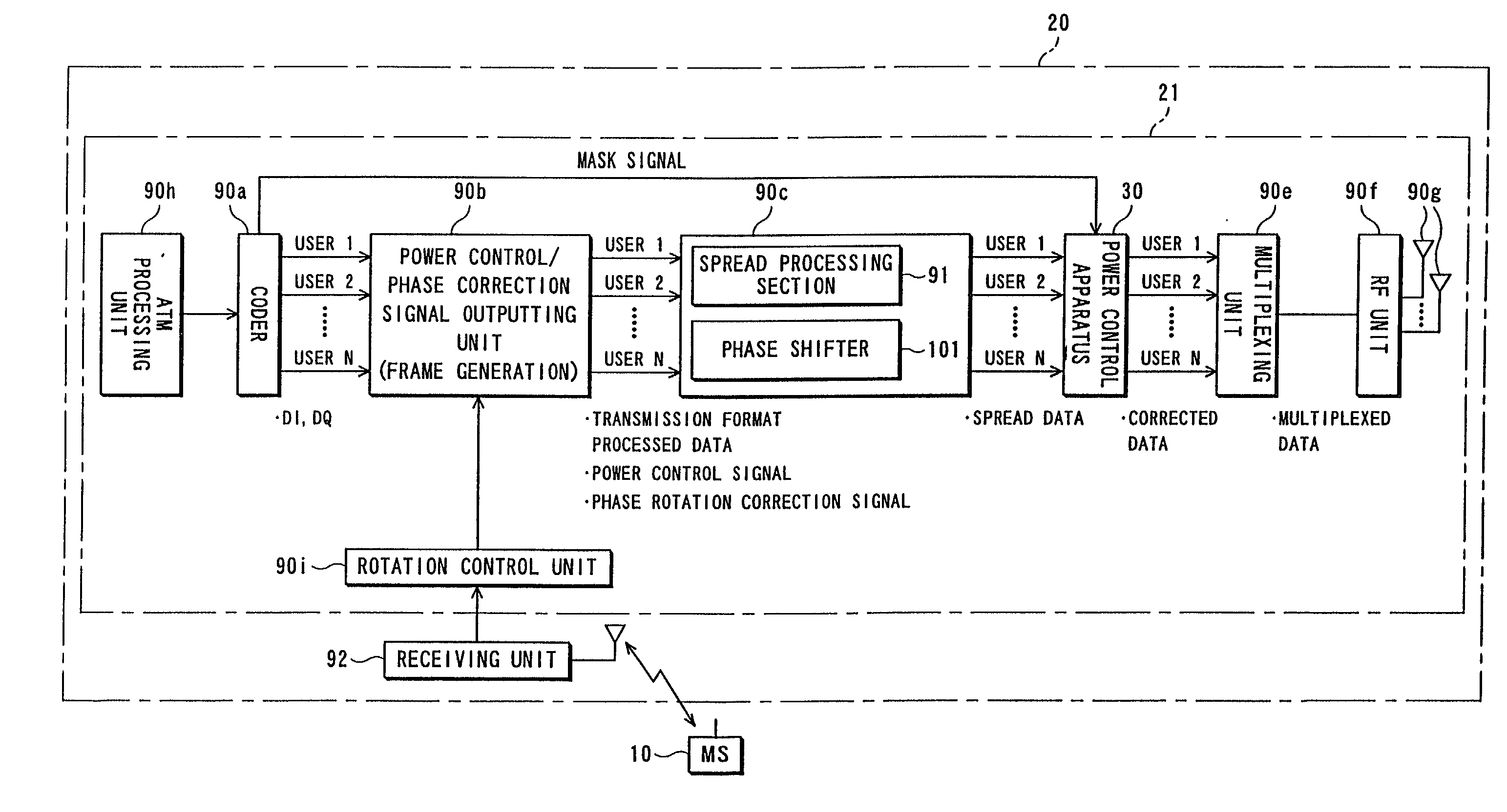
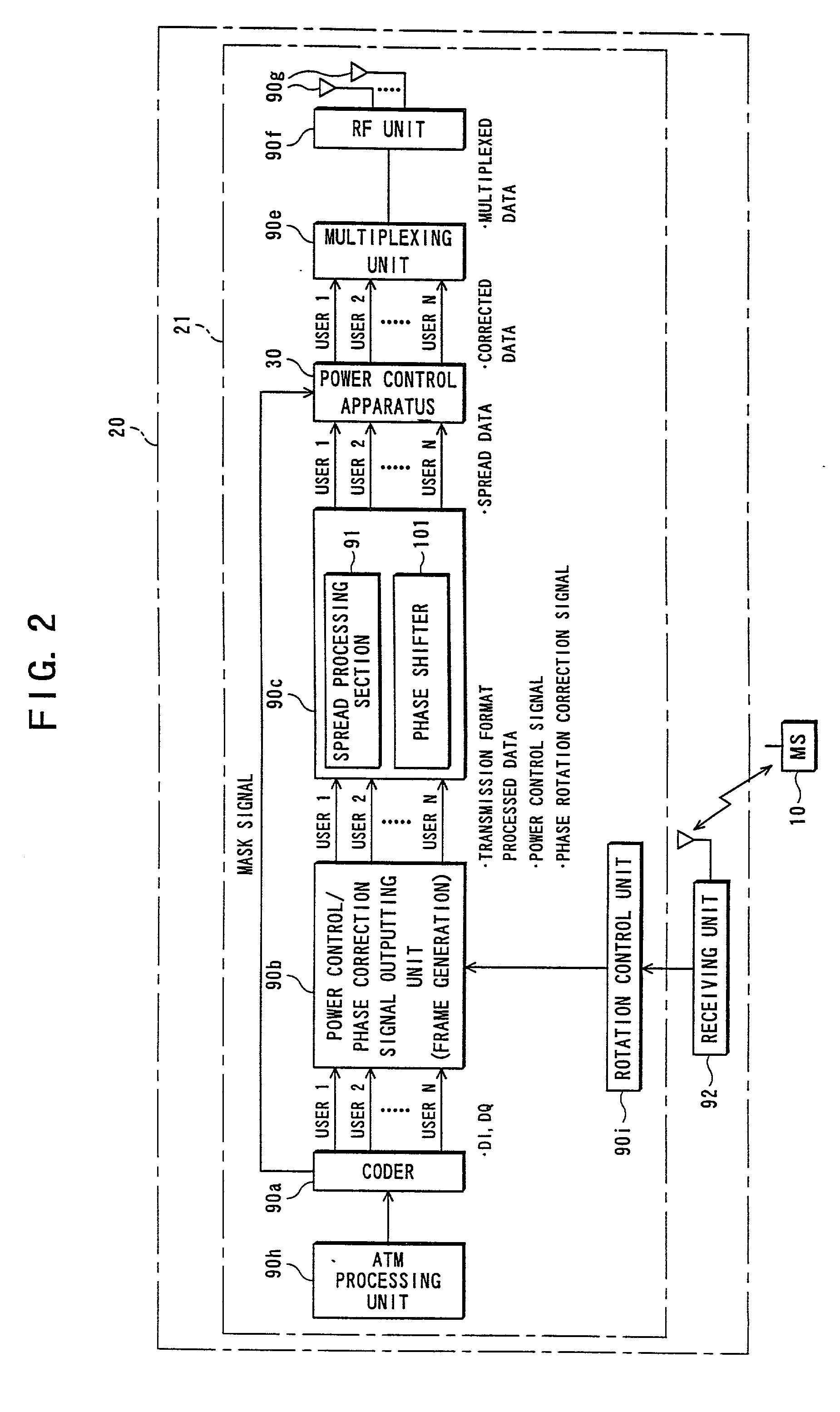
[0101] FIG. 2 is an illustration of an essential part of a transmitter of the base station 20 according to the present invention. As FIG. 2 shows, the base station 20 includes, in addition to a receiving unit 92 for receiving an RF signal from the mobile stations (MS) 10, a transmitting apparatus 21 which is for multiplexing signals outputted from the ATM network 80 and converting them into an RF signal. This transmitting apparatus 21 is composed of an ATM processing unit 90h, a coder 90a, a power control / phase correction signal outputting unit 90b, a spread processing / phase rotating unit 90c, a power control apparatus 30, a multiplexing unit 90e, an RF unit 90f, antennas 90g and a rotation control unit 90i.

[0102] The ATM processing unit 90h is for receiving a signal (ATM signal) stacked through the use of an ATM protocol to perform format conversion of this ATM signal. Concretely, the ATM processing unit 90h terminates ATM data outputted from the ATM network 80 and outputs it as, f...

second embodiment

[0218] (B) Description of Second Embodiment of the Invention

[0219] FIG. 20 is a block diagram showing a power control apparatus according to a second embodiment of the present invention. A power control apparatus 30f shown in FIG. 20 is for performing power control or power correction of spread data for each user, outputted from the spread processing / phase rotating unit 90c. This power control apparatus 30f differs from the power control apparatus 30 according to the first embodiment in that the phase rotation based on the nine-point constellation is not made. Also in the second embodiment, the configurations of the system 100 and the base station 20 are similar to those described as the first embodiment, and the description thereof will be omitted for brevity.

[0220] In the power control apparatus 30f, power control information outputted from the spread processing / phase rotating unit 90c is directly inputted to a phase rotation correcting section 14 without being phase-rotated in th...

third embodiment

[0224] (C) Description of Third Embodiment of the Invention

[0225] A description of a third embodiment will be made about a four-point constellation (see FIG. 5).

[0226] FIG. 21 is a block diagram showing a power control apparatus according to a third embodiment of the present invention. In FIG. 21, a power control apparatus 30g is designed to perform power control or power correction of spread data for each user, outputted from the spread processing / phase rotating unit 90c, and is composed of a power correcting section 1e and a power control section 200.

[0227] The power correcting section 1e is for correcting an amplitude value of a symbol before phase rotation on the basis of a decision signal representative of need / non-need for correction the symbol amplitude value before the phase rotation and a mask signal indicative of at least one of symbol point components being masked to input the corrected amplitude value to the power control section 200. This power correcting section 1e is ...


PUM


Abstract

The present invention relates to a transmitting unit of a base station using CDMA system, where a power control apparatus is provided which comprises a power control section and a power correcting section. The power correcting section is composed of a mask signal correcting section for correcting power control information about transmission on the basis of mask signals to output the corrected power control information, a phase rotation correcting section for correcting the corrected power control information on the basis of a decision signal to input the resultant corrected amplitude value to the power control section, and a symbol arrangement information arithmetic section for outputting symbol arrangement information based on each of the mask signals to the mask signal correcting section and the phase rotation correcting section. With this configuration, it is possible to reduce or cut the circuit scale, thus promoting an increase in user capacity.

Description

[0001] (1) Field of the Invention[0002] The present invention relates to, for example, in a transmitter employing a nine-point constellation (arrangement of nine symbol points) involving mask signals, a power control apparatus and power control method suitable for use in a power correcting circuit for transmission symbols after rotation of symbol phases.[0003] (2) Description of the Related Art[0004] In the recent years, the code division multiple access system (which will be referred to hereinafter as "CDMA") has been used as a standard of radio communication systems applicable to mobile units or the like. A feature of this CDMA is not only accommodating a large number of subscribers but also providing excellent resistance to fading and interference and even offering high frequency efficiency.[0005] In addition, a transmitting apparatus (transmitter) included in a base station or mobile station primary-modulates data through the use of QPSK (Quadrature Phase Shift Keying) modulatio...

Claims


Application Information

Patent Timeline
IPC IPC(8): H04L27/20H04B1/04H04B7/005H04B7/26H04L27/36H04L27/38
CPCH04L27/3809H04L27/3854H04W52/58
Inventor SEKI, TETSUYA
Owner FUJITSU LTD
Why Eureka
Try Eureka