Twin spark ignition coil with provisions to balance load capacitance

Inactive Publication Date: 2007-09-13
DELPHI TECH INC
View PDF18 Cites 5 Cited by
  • Summary
  • Abstract
  • Description
  • Claims
  • Application Information

AI Technical Summary

Benefits of technology

[0009] An object of the present invention is to solve one or more of the problems set forth in the Background. The present invention is provided generally to provide a structure to offset and thus balance the capacitance imbalance that might otherwise be seen between the two HV outputs of a twin spark ignition coil, arising due to the

Problems solved by technology

A problem with the plug top ignition coil for twin spark operation however, relates packa

Method used


Image

  • Twin spark ignition coil with provisions to balance load capacitance
  • Twin spark ignition coil with provisions to balance load capacitance
  • Twin spark ignition coil with provisions to balance load capacitance

Examples


case 42

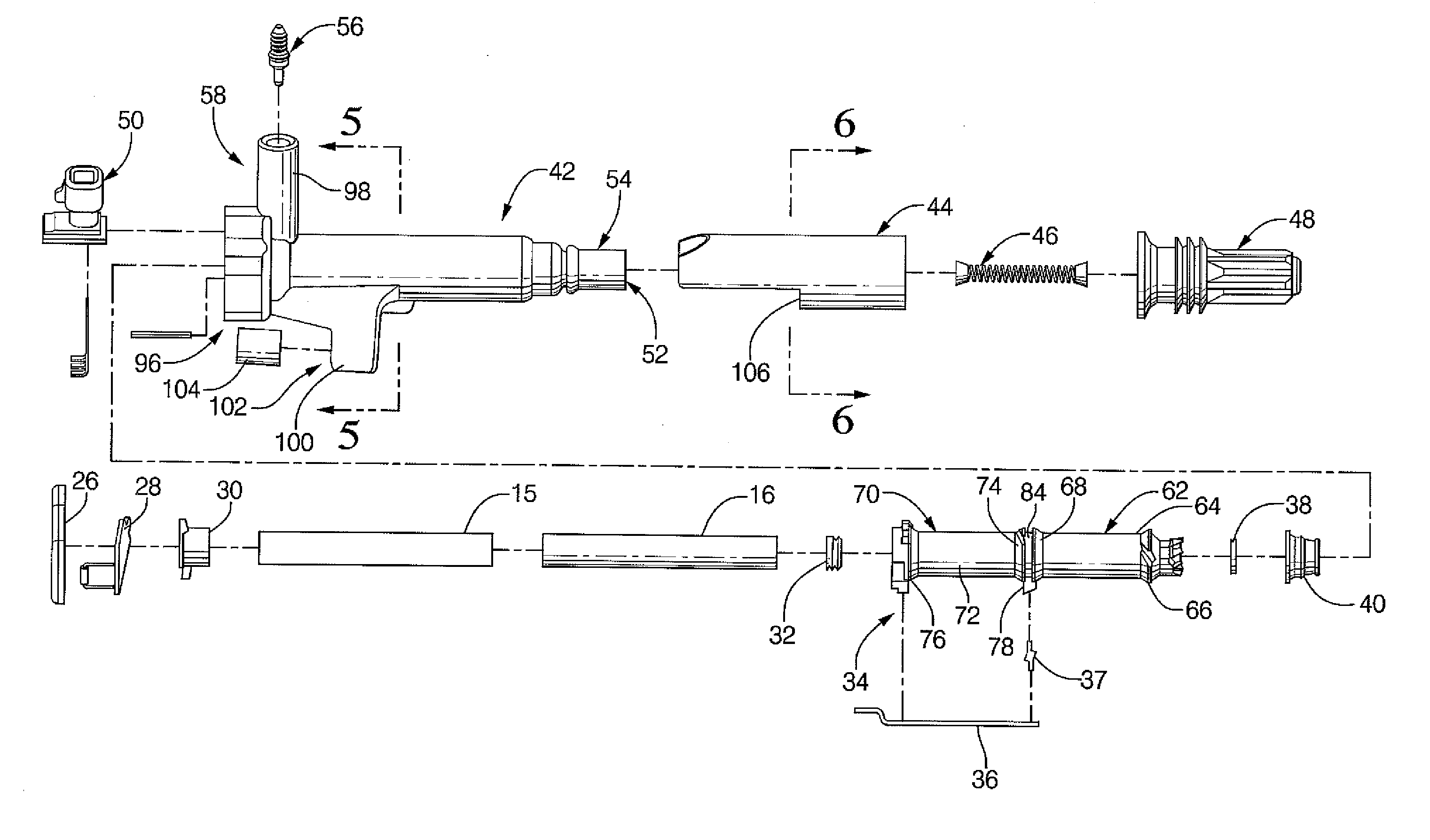
[0066] Case 42 further includes system connector 50, which includes conductive terminals arranged for connection to a mating terminal (not shown) for communication of power and control signals between the ignition apparatus 10 and an ignition system controller or other master controller (not shown).

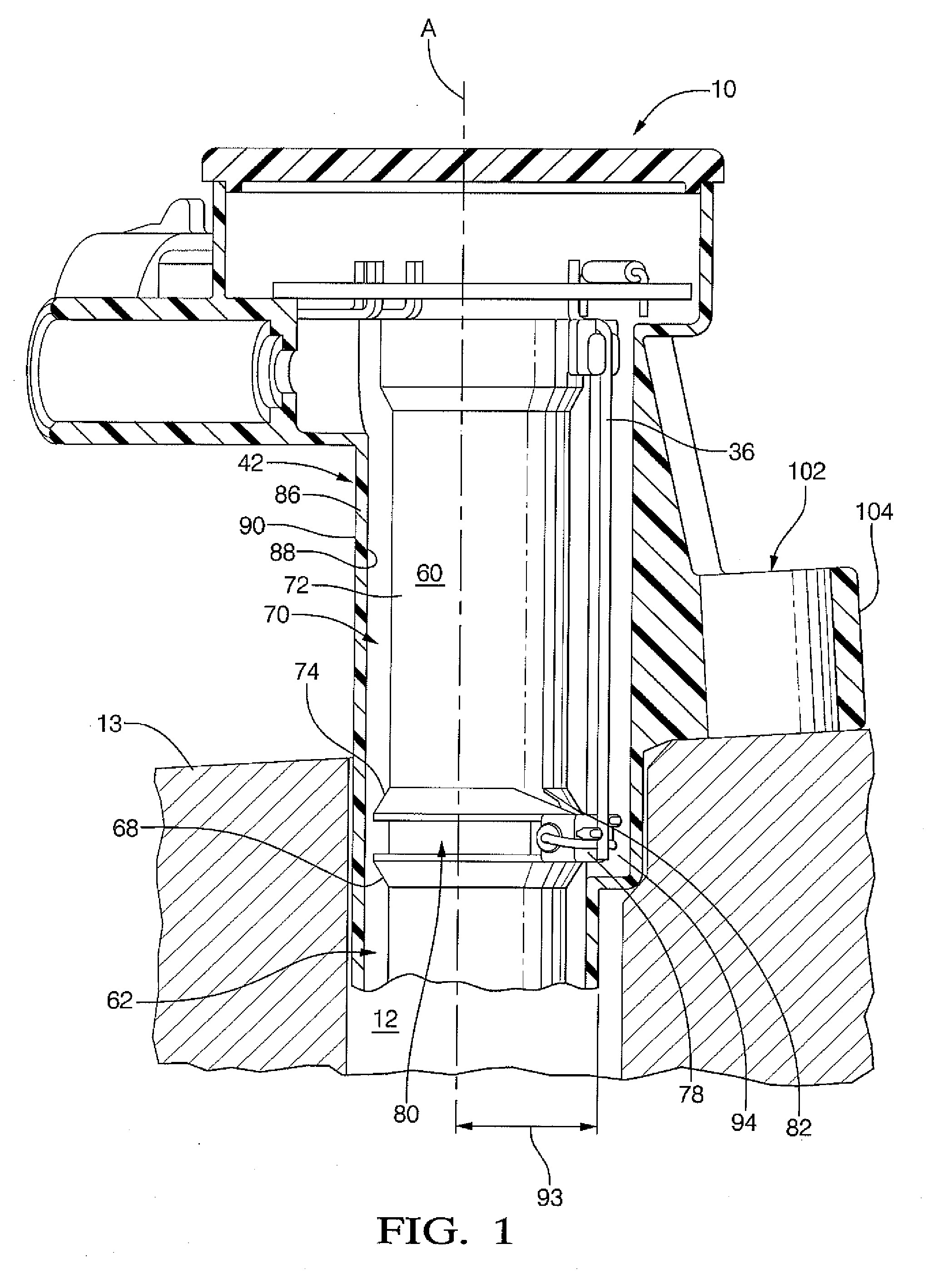
[0067] Case 42 may optionally further includes a mounting flange 100 containing a through bore 102 adapted in size and shape to receive a bushing 104. Mounting flange 100 provides a mechanism to allow the optional connection of ignition apparatus 10 to engine 13 or other portion of the engine compartment. Note, the ignition apparatus 10 may be relatively rigidly coupled via the direct connection of first HV output 52 to a spark plug in the spark plug well 12.

[0068] Inner surface 88 or inside diameter (ID) of case 42 is configured in size to receive and retain the assembly comprising core 15 / primary winding 16 / secondary spool 34 / secondary winding 18. The inner surface 88 may be slightly s...

first embodiment

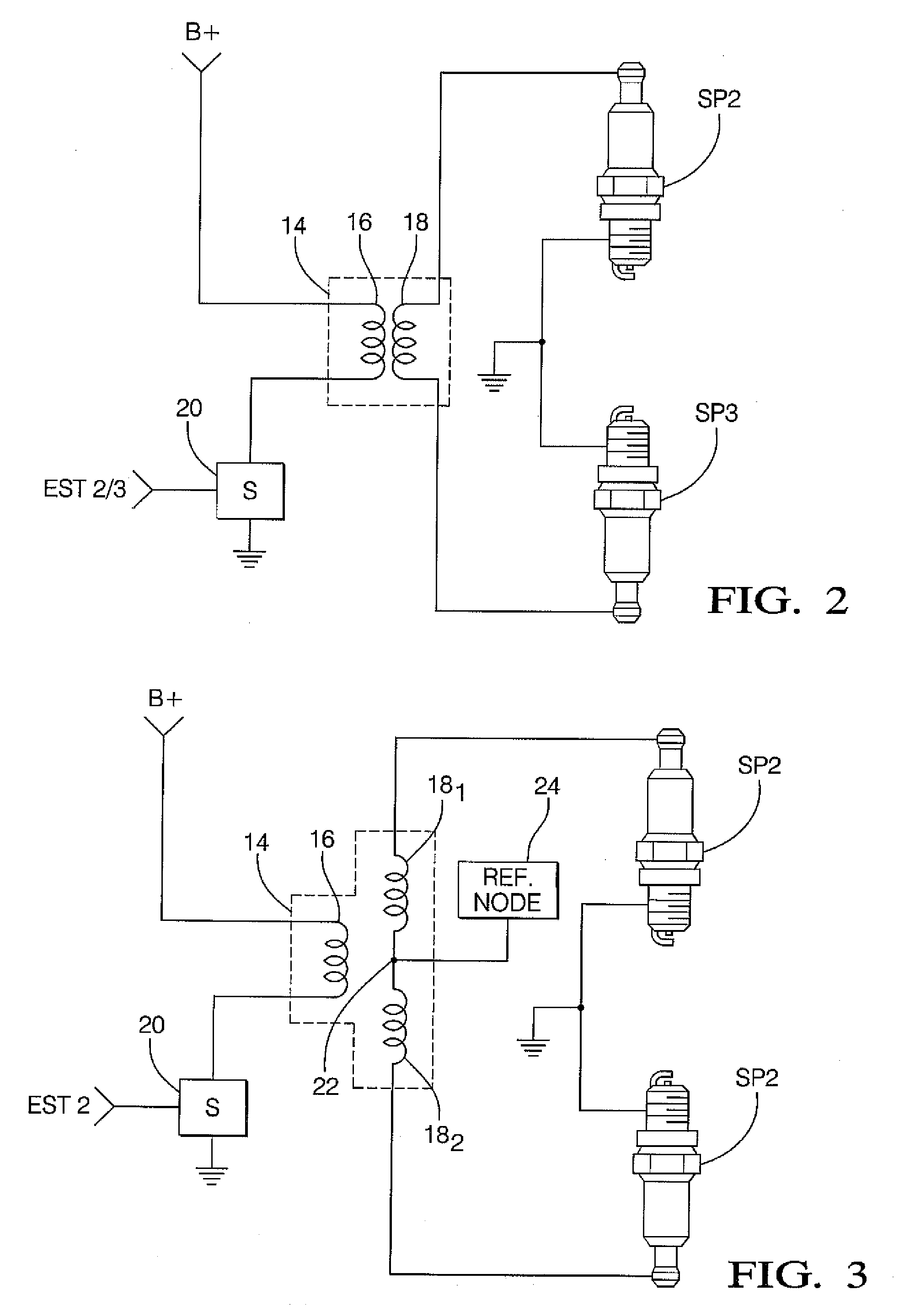
[0082]FIGS. 10-19 depict additional illustrative embodiments of the present invention. The ignition coil 10 of the first embodiment utilizes a progressive winding for a “pencil” coil twin spark application. In that embodiment, the coil 10 has a first HV connection that mounts directly to a one spark plug while a second HV connection provides a spark voltage to another spark plug. The second HV connection may be coupled to (i) a mated cylinder on the exhaust stroke (i.e., while the first HV connection goes to the cylinder in compression) or (ii) to another plug in the same cylinder in compression. This ignition coil arrangement may be provided with a center-tapped secondary winding wherein the two portions formed are wound in opposite orientations to provide two negative sparks to two spark plugs in the same cylinder. However, a characteristic of this embodiment is that such a configuration limits the output of the second HV connection after the breakdown of the first HV connection. ...

case 214

[0085] Case 214 extends along a main axis designated “A” in FIG. 10, and is configured to house transformer assembly 212. Case 214 includes a first high-voltage (HV) connection 216 proximate or near a first longitudinal end 218. First HV connection 216 is configured for direct mounting on a first spark plug, which is designated SP3 in FIG. 10. First spark plug SP3 may be disposed in a first spark plug well 2201 formed in an internal combustion engine 222. The first HV connection 216 has a first capacitance C1 associated therewith when directly mounted to the first spark plug (“SP3”).

[0086] Case 214 further includes a second high-voltage (HV) connection 224 proximate a second longitudinal end 226. Second end 226 is axially opposite first end 218 in the illustrative embodiment. Second HV connection 224 is configured for connection to a second spark plug (designated SP2 in FIG. 10) via a high-voltage (HV) distribution mechanism 228. Second spark plug SP2 may be disposed in a second spa...


PUM


Abstract

A twin spark ignition apparatus having two high-voltage (HV) outputs incorporates features for balancing load capacitance on each HV output. The ignition apparatus provides a first high-voltage (HV) connection configured for direct mounting on a first spark plug, and a second HV connection for coupling to a second spark plug by way of an HV cable. The HV cable adds capacitance at the second HV output, as compared to a direct mount. The secondary winding is shifted by a predetermined distance, relative to the primary winding, in direction toward the direct mount end of the ignition apparatus. The shifting reduces the internal load capacitance at the second end (top), so that when the capacitance added by the HV cable is considered, the respective load capacitances are balanced. The voltage variation between the two HV outputs is reduced.

Description

CROSS-REFERENCES TO RELATED APPLICATIONS [0001] This is a continuation-in-part (CIP) application of U.S. application Ser. No. 11 / 556,836 filed Nov. 6, 2006, now pending, which is continuation-in-part (CIP) of U.S. application Ser. No. 11 / 041,004 filed Jan. 24, 2005, now U.S. Pat. No. 7,148,780, the entire disclosures of each application Ser. Nos. 11 / 041,004 and 11 / 556,836 are hereby incorporated by reference in their entireties herein.BACKGROUND OF THE INVENTION [0002] 1. Technical Field [0003] The present invention relates generally to an ignition apparatus or coil, and, more particularly, to a twin spark pencil coil with provisions to balance load capacitance. [0004] 2. Discussion of the Background Art [0005] An ignition apparatus for producing a spark for ignition of an internal combustion engine has been developed in a variety of different configurations suited for the particular application desired. For example, it is known to provide an ignition apparatus that utilizes a secon...

Claims


Application Information

Patent Timeline
IPC IPC(8): F02P3/02
CPCF02P3/02F02P3/0407F02P15/08H01T13/44H01F38/12H01F2038/122H01F27/34
Inventor SKINNER, ALBERT A.LEVERS, HARRY O.
Owner DELPHI TECH INC
Why Eureka
Try Eureka