
Magnetic sensor, method of manufacturing the same, and electronic device

Active Publication Date: 2007-09-13
MURATA MFG CO LTD
View PDF2 Cites 4 Cited by
  • Summary
  • Abstract
  • Description
  • Claims
  • Application Information

AI Technical Summary

Benefits of technology

[0017]It is therefore an object of the present invention to provide a magnetic sensor that detects two or more different magnetic fields, uses an alloy metal thin film having a magnetic resistance sufficiently changed in a wide range from the low magnetic field side to the high magnetic field side, and is scarcely affected by film stresses, and has small restrictions on processes. It is another object of the present invention to provide a method of manufacturing such a magnetic sensor. It is also still another object of the present invention to provide an electronic device using such a magnetic sensor.
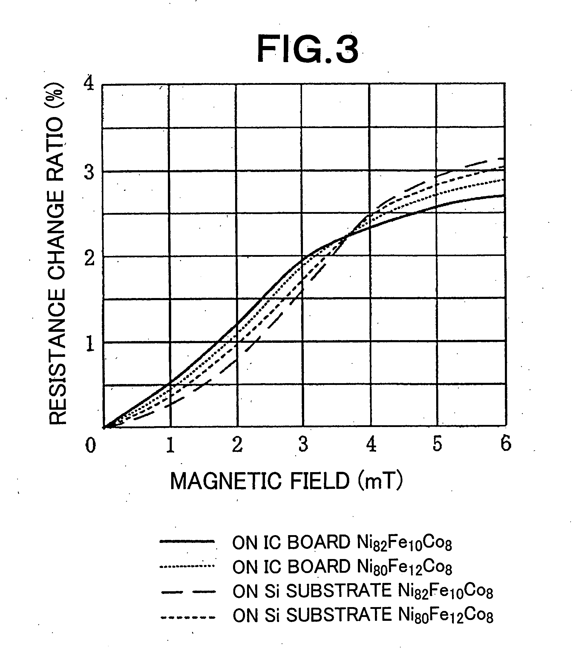
[0029]By fulfilling the magnetic characteristics, it becomes possible to sufficiently make a magnetic sensor operate, which detects two or more magnetic fields, at least one of which magnetic fields to be detected is 2.5 mT or more, among whose plural magnetic fields to be detected, the minimum magnetic field to be detected and the maximum magnetic field to be detected are separated by 0.5 mT or more. That is, the magnetic sensor detects two or more different magnetic fields, because the alloy metal thin film has a magnetic resistance sufficiently changed in a wide range from the low magnetic field side to the high magnetic field side, especially about each of the magnetic fields to be detected.
[0031]As has been described above, according to the present invention, it becomes possible to obtain a magneto-resistance effect thin film whose magnetic resistance is changed in a wide region from the low magnetic field side to the high magnetic field side, and is scarcely affected by film stresses, and is not required to undergo the annealing before the patterning process for the magneto-resistance effect thin film, and has small restrictions on processes. As a result, it becomes possible to provide a magnetic sensor that detects two or more magnetic fields, at least one of which magnetic fields to be detected is 2.5 mT or more, among whose plural magnetic fields to be detected, the minimum magnetic field to be detected and the maximum magnetic field to be detected are separated by 0.5 mT or more, and an electronic device using the magnetic sensor.

Problems solved by technology

However, so as to get the magnetic resistance change ratio, a heat treatment of 200° C. or more as well as 400° C. or less is necessary prior to the patterning process for the magneto-resistance effect thin film, which restricts processes.
Especially, in case of realizing a magnetic sensor that can detect a high magnetic field of 2.5 mT [milli-tesla] or more in magnetic flux density, a conventional NiFe thin film that has its magnetic resistance changed in a narrow magnetic field range cannot attain the magnetic sensor even if the magnetic sensitivity thereof is high.
As a result, it becomes difficult to set the magnetic characteristics in a targeted range, which undesirably lowers the yield ratio of the magnetic sensor.

Method used


Image

  • Magnetic sensor, method of manufacturing the same, and electronic device
  • Magnetic sensor, method of manufacturing the same, and electronic device
  • Magnetic sensor, method of manufacturing the same, and electronic device

Examples


Embodiment Construction

[0047]The present invention will further be described below with reference to the accompanying drawings.

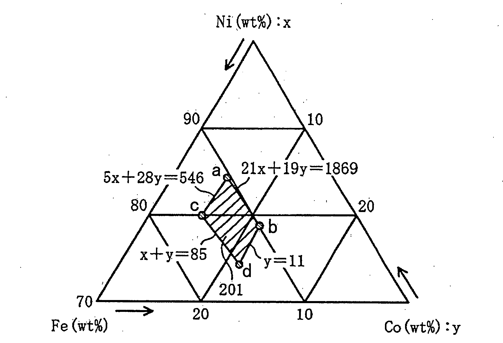
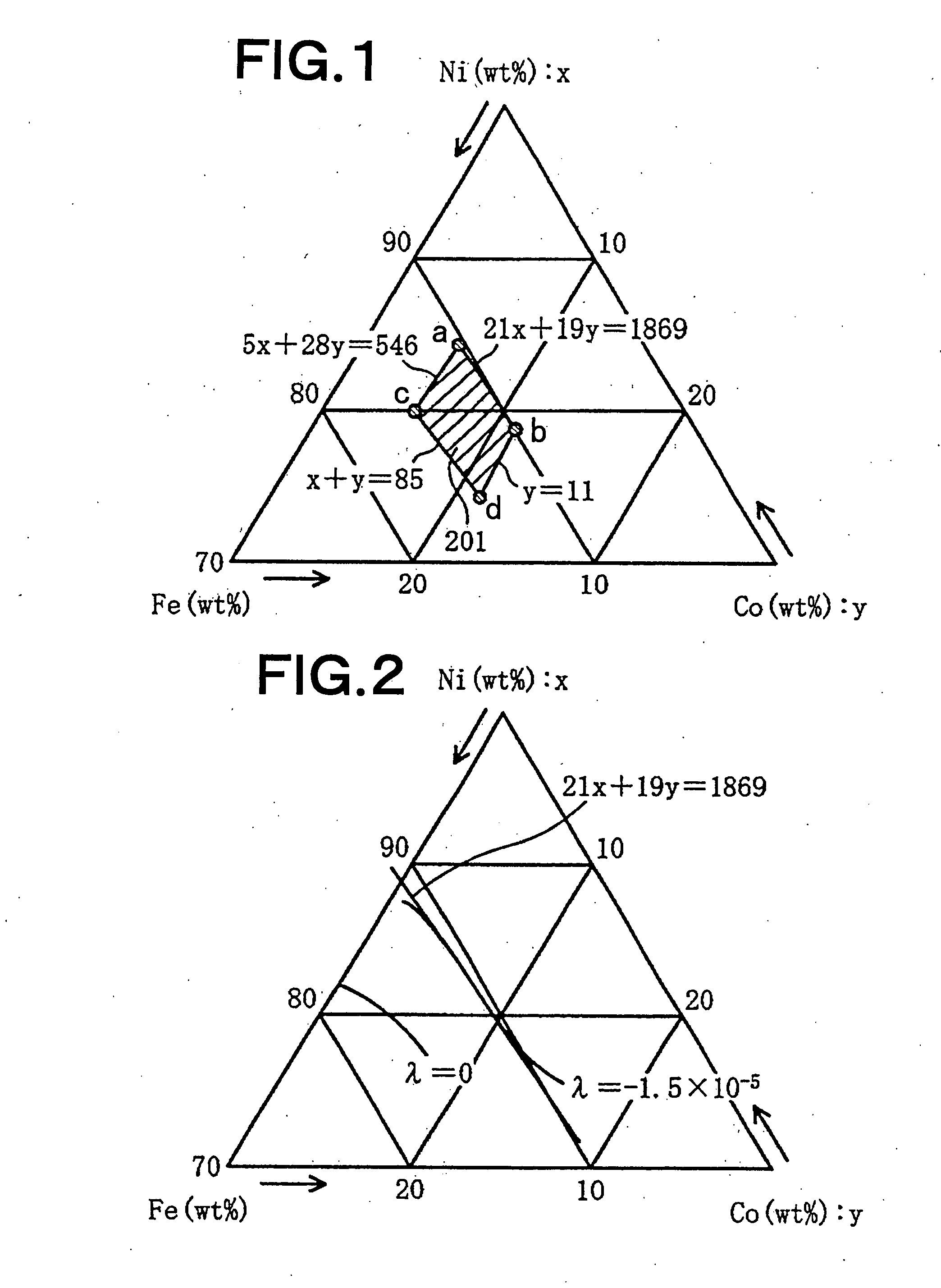
[0048]FIG. 1 is a diagram indicative of the composition range of a magneto-resistance effect thin film (referred to as magnetic film arbitrarily, hereinafter) as an alloy metal thin film which is used as a magnetic resistance element of a magnetic field sensing portion in a magnetic sensor according to an embodiment of the present invention. The magneto-resistance effect thin film used in this embodiment is an alloy metal thin film including Ni, Fe and Co as main components. The alloy metal thin film is within a composition range that concurrently fulfills the following mathematical expressions of (1) to (4), where the composition ratio of Ni is represented by x % by weight, while the composition ratio of Co is represented by y % by weight:

21x+19y≦1869   (1)

5x+28y≧546   (2)

y≦11   (3)

x+y≧85   (4)

[0049]Area within the composition range that concurrently fulfills the mathematical exp...


PUM


Abstract

A magnetic sensor have a magnetic field sensing portion having an alloy metal thin film including Ni, Fe and Co as main components and having a magneto-resistance effect, and detects two or more magnetic fields, at least one of which magnetic fields to be detected is 2.5 mT or more, and among which magnetic fields to be detected the minimum magnetic field and the maximum magnetic field are separated by 0.5 mT or more. The alloy metal thin film has an absolute value of magneto-striction constant of 1.5×10⁻⁵ or less, an anisotropic magnetic field of 8 Oe or more as well as 16 Oe or less, and a magnetic resistance change ratio of 2.5% or more. The alloy metal thin film is within a composition range which concurrently fulfills the following relations: 21x+19y≦1869, 5x+28y≧546, y≦11, and x+y≧85, where the composition ratio of Ni is represented by x % by weight, while the composition ratio of Co is represented by y % by weight.

Description

BACKGROUND OF THE INVENTION[0001]1. Field of the Invention[0002]The present invention relates to a magnetic sensor that detects a magnetic field by utilizing the magneto-resistance effect, a method of manufacturing the same, and an electronic device using the magnetic sensor, and more particularly, to a magnetic sensor that can detect two or more different magnetic fields, a method of manufacturing the same, and an electronic device such as a flip phone or folded-type cellular phone that can detect a displacement of a part of member such as a part of housing using the magnetic sensor.[0003]2. Description of Related Art[0004]A magnetic sensor that detects a magnetic field by employing the anisotropic magneto-resistance effect is called also an MR (Magneto-Resistance) sensor. The magnetic sensor is widely used in a rotation detection device that detects the rotation of an object, in a position detection device that detects the relative position between objects, and in an opening / closi...

Claims


Application Information

Patent Timeline
IPC IPC(8): G01B7/14G01R33/02
CPCG01R33/09
Inventor MITSUZUKA, TSUTOMU
Owner MURATA MFG CO LTD
Learn More