Static mixing element and method of mixing a drilling liquid

Inactive Publication Date: 2007-09-13
TT SCHMIDT
View PDF61 Cites 4 Cited by
  • Summary
  • Abstract
  • Description
  • Claims
  • Application Information

AI Technical Summary

Benefits of technology

[0016] The invention is accordingly based on the object of providing a static mixer which makes possible efficient homogenization and dispersion of various media with constructionally simple mixer elements, which can additionally be produced cost-effectively and are simple to clean.

Problems solved by technology

These mixing systems have an increased requirement for space and lead to time delays in the drilling operation if, after a batch of drilling liquid has been used, a new batch has to be prepared.
They do not permit a compact design of the overall drilling system.
A considerable disadvantage of the known static mixers resides in the fact that the mixer elements, produced with complex geometry, have to be produced in complicated production processes, which give rise to a considerable expenditure in time and cost.
Above all, the partly solid configuration of the mixers with differently aligned passages makes a high expenditure on material necessary.
A further disadvantage of known mixers is that cleaning of the mixers is made considerably more difficult, because of the deflection surfaces being at changing angles to one another Reliable, simple cleaning, for example by means of a cleaning fluid merely flowing through the mixer, is inadequate.

Method used


Image

  • Static mixing element and method of mixing a drilling liquid
  • Static mixing element and method of mixing a drilling liquid

Examples


Embodiment Construction

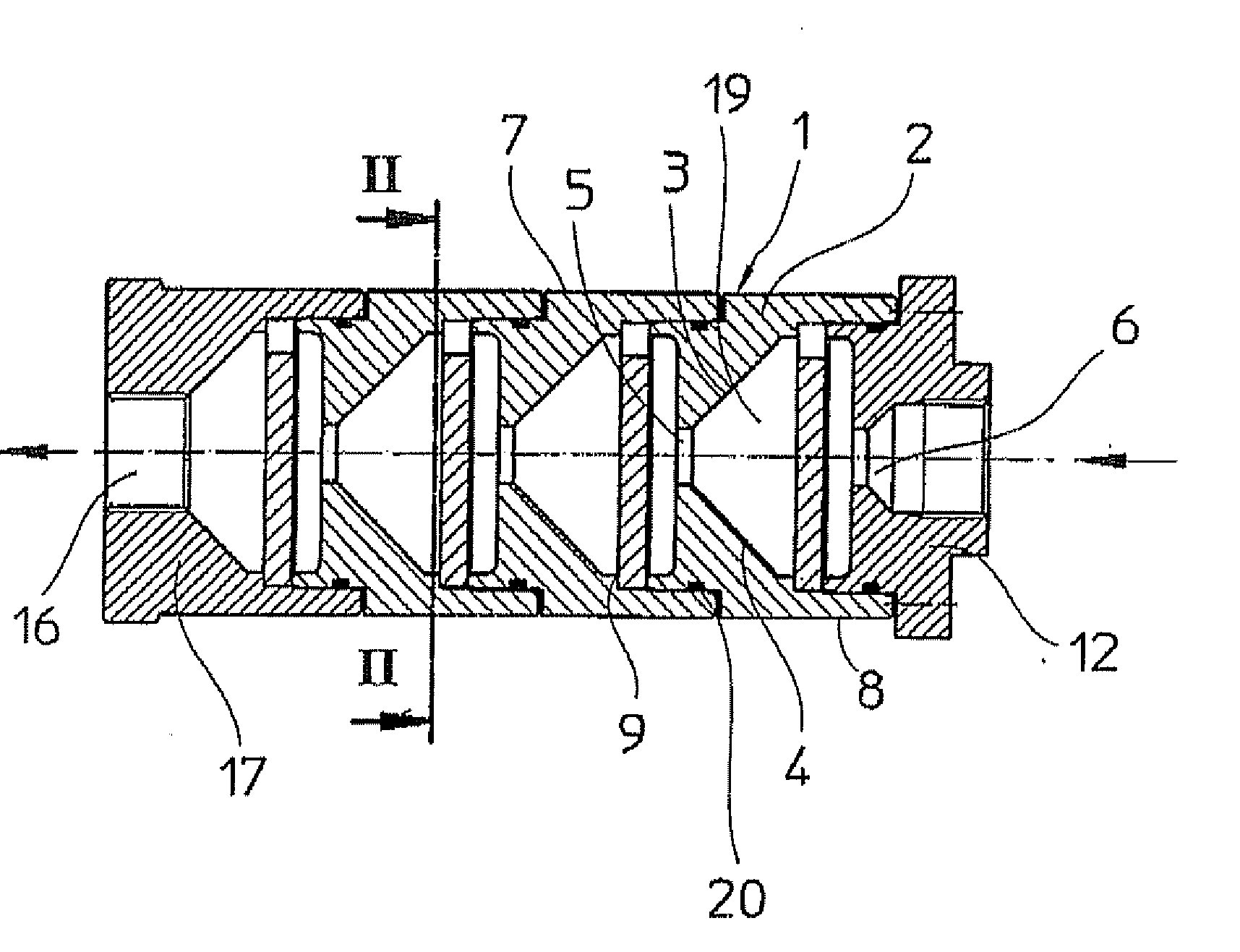
[0037] An individual element 1 of the mixing system comprises a housing 2 with two inclined surfaces 3 and 4, which narrow in the manner of a funnel toward a passage opening 5. They allow the passage of the medium flowing into the mixing system through the inlet opening 6 in the direction of the arrow.

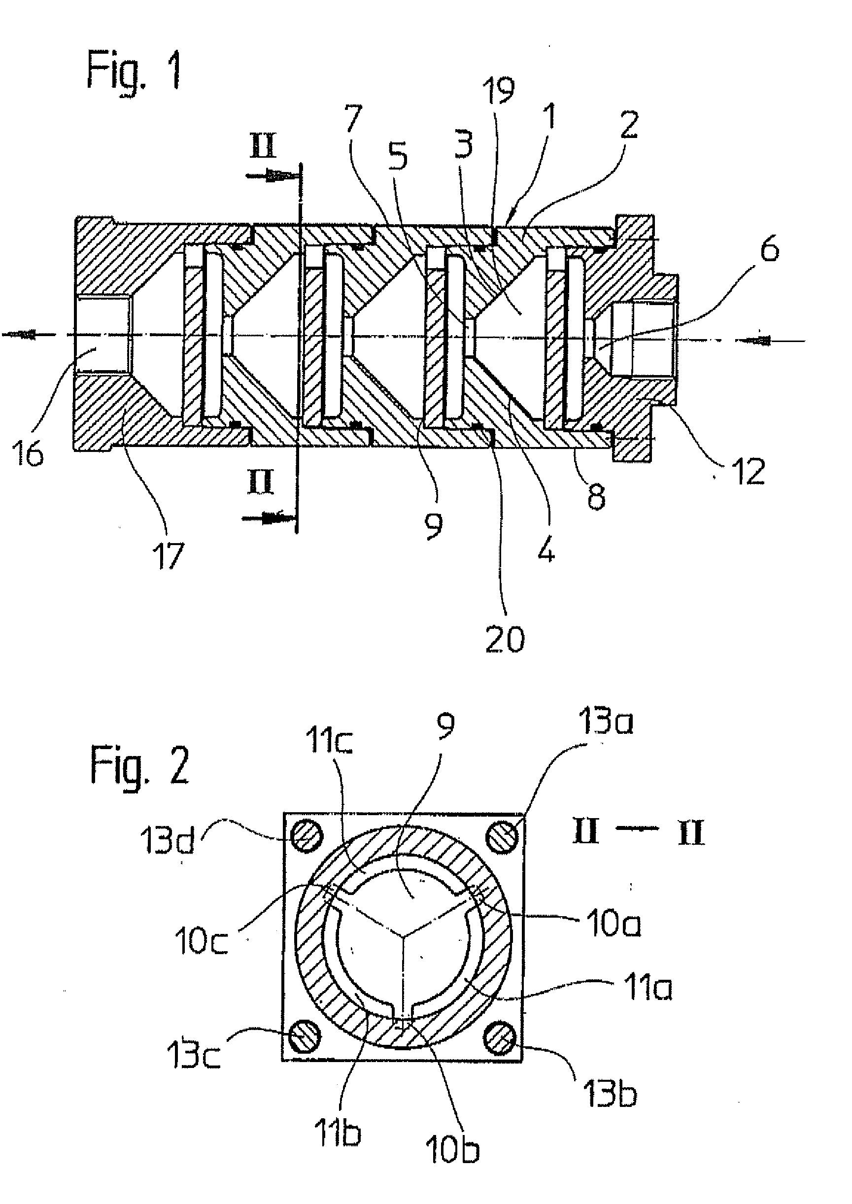
[0038] The deflection surface 9, at right angles to the outer surfaces 7, 8 of the housing, is clamped between the housings 2 by three tongues 10a, 10b, 10c. In comparison to the housing, it has a smaller radius, so that passages 11a, 11b, 11c remain free between the housing 2 and the deflection surface 9. Parts 13a to d represent tie rods, which pull the top piece 12 and the end piece 17 toward each other and in this way clamp the deflection surfaces 9 firmly through the housings 2.

[0039] In the exemplary embodiment, a mixing system is assembled from three individual elements each having a deflection surface and a top piece 12 and an end piece 17. These are sealed off from one anoth...


PUM


Abstract

Static mixer element for homogenizing media and methods of mixing a drilling liquid are disclosed. The static mixer includes a housing and a deflection surface arranged within the housing at a selected angle with respect to the flow direction.

Description

CROSS-REFERENCE TO RELATED APPLICATIONS [0001] This application is a continuation of and claims priority to U.S. patent application Ser. No. 10 / 257,830, which is a U.S. national stage application of International Application No. PCT / EP01 / 04516, filed Apr. 20, 2001, which claims foreign priority to German Patent Application 100 19 759.0-23, filed Apr. 20, 2000, the contents of all of the above applications are hereby incorporated by reference.BACKGROUND OF THE INVENTION [0002] Increasingly high requirements are placed on homogenizing and dispersing media of the same or different aggregate states as a precondition of a large number of process steps in chemical or engineering technology, said requirements having to be met with the aid of generally complex static or dynamic mixing systems. [0003] During horizontal drilling, too, there is the requirement to mix a liquid with a powdered substance or a liquid or a suspension if, in order to facilitate and improve the drilling operation, fo...

Claims


Application Information

Patent Timeline
IPC IPC(8): B01F5/06B01F13/10
CPCB01F5/0646B01F5/0651B01F2013/1052B01F5/0688B01F13/1013B01F5/0682B01F25/4334B01F25/433B01F25/45B01F25/4521B01F33/81B01F33/834
Inventor SCHAUERTE, MANFRED
Owner TT SCHMIDT
Why Eureka
Try Eureka