Image forming apparatus

a technology of image forming apparatus and forming sheet, which is applied in the direction of electrographic process apparatus, instruments, optics, etc., can solve the problems of reducing the heat dissipation efficiency of the image forming apparatus, deteriorating toner, and difficulty in maintaining the temperature below the specific temperature, so as to reduce frictional heat, prevent deterioration of the developer, and reduce the flow characteristic of the developer

Inactive Publication Date: 2007-09-13
OKI DATA CORP
View PDF11 Cites 16 Cited by
  • Summary
  • Abstract
  • Description
  • Claims
  • Application Information

AI Technical Summary

Benefits of technology

[0011]In particular, the external temperature detection unit detects the environmental temperature outside the image forming apparatus; and the control unit sets the driving speed of the driving unit according to the environmental temperature. Accordingly, it is possible to reduce frictional heat. As a result, it is possible to maintain a temperature of developer below a specific temperature. Therefore, it is possible to prevent deterioration of developer, lowered flow characteristic of developer, and improper charging.
[0012]Further, in the present invention, it is possible to reduce heat conducted to a sheet through lowering the driving speed, thereby making it possible to reduce a fixing temperature. Further, it is possible to prevent the driving unit from generating excessive heat. Accordingly, even when a plurality of images is formed sequentially, it is possible to prevent a temperature inside the image forming apparatus from rising.

Problems solved by technology

However, when the image forming apparatus is installed in a relatively high temperature environment, discharging efficiency of heat of the image forming apparatus is lowered.
However, when the image forming apparatus is installed in a relatively high temperature environment, in which discharging efficiency of heat of the image forming apparatus is lowered, it may be difficult to maintain the temperature below the specific temperature even in the intermittent printing operation.
As a result, the image forming apparatus may stay in a relatively high temperature environment for a long period of time, thereby deteriorating toner.

Method used


Image

  • Image forming apparatus
  • Image forming apparatus
  • Image forming apparatus

Examples


first embodiment

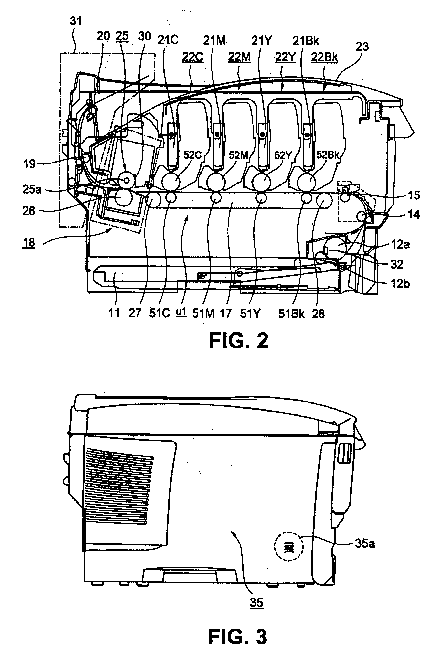
[0036]A first embodiment of the present invention will be explained. FIG. 2 is a schematic view showing a printer according to the first embodiment of the present invention.

[0037]As shown in FIG. 2, a sheet supply cassette 11 is disposed at a lower portion of the printer as a recording medium storage portion for storing sheets (not shown) as recording media. A sheet supply mechanism is disposed adjacent to the sheet supply cassette 11 for separating and supplying the sheet one by one.

[0038]The sheet supply mechanism includes sheet supply rollers 12a and 12b. After being supplied with the sheet supply mechanism, the sheet is transported to a transport roller 14 disposed at an upper portion, and further to a transport roller 15. Afterward, a transport belt 17 as a transport member or a first transfer member is driven to rotate with a belt motor (described later) as a driving unit for belt transportation. Accordingly, the transport belt 17 transports the sheet further, so that the shee...

second embodiment

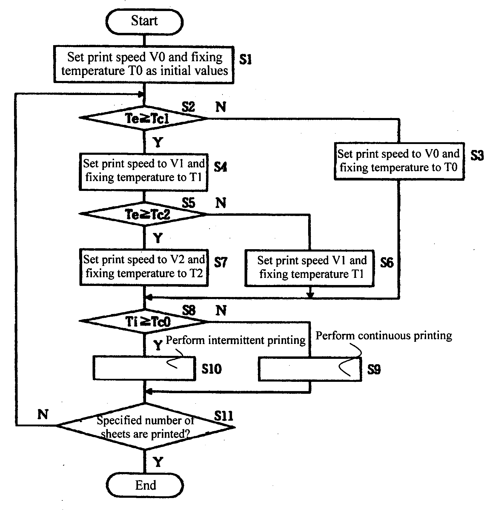
[0116]In general, the sheet has a temperature equal to or higher than the environmental temperature outside the printer, and equal to or lower than the temperature inside the printer. Accordingly, when a small number of sheets are printed for a short period of time, the sheet tends to cool the surfaces of the photosensitive drums 52Bk, 52Y, 52M, and 52C. In contrast, when a large number of sheets are printed for a long period of time, the temperature inside the printer tends to increase rather quickly due to heat generated from the ID motor 76, the transportation motor 78, the fixing motor 82, and the image forming units 22Bk, 22Y, 22M, and 22C.

[0117]In a second embodiment of the present invention, the number of printed sheets during a specific period of time is measured, thereby controlling the temperatures of the image forming units 22Bk, 22Y, 22M, and 22C according to the environmental temperature outside the printer.

[0118]In the second embodiment, components similar to those in ...

third embodiment

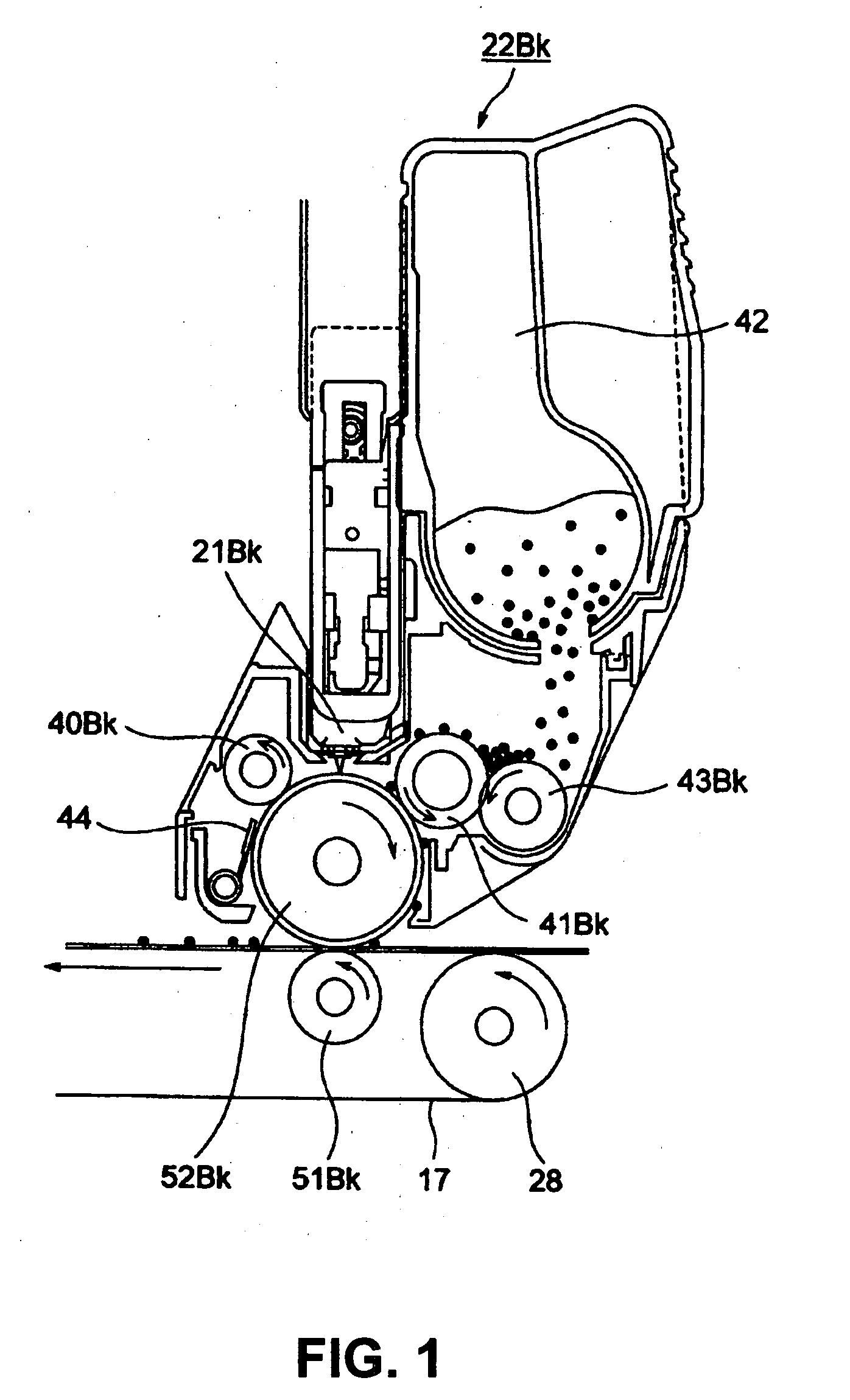
[0145]In the image forming units 22Bk, 22Y, 22M, and 22C, when the ID motor 76 starts driving, the photosensitive drums 52Bk, 52Y, 52M, and 52C; the charging rollers 40Bk, 40Y, 40M, and 40C; and the developing rollers 41Bk, 41Y, 41M, and 41C rotate. Further, the transport belt motor control unit 79 drives the transportation belt motor 80 to transport the sheet, and in the fixing device 18, the fixing motor 82 is driven to rotate the fixing roller 25 and the pressing roller 26.

[0146]In a third embodiment of the present invention, a period of powered time as an operation time of each of the ID motor 76, the transportation belt motor 80, and the fixing motor 82 is measured, thereby controlling the temperature of the image forming units 22Bk, 22Y, 22M, and 22C according to the environmental temperature outside the printer.

[0147]In the third embodiment, components similar to those in the first and second embodiments are designated by the same reference numerals, and explanations thereof ...


PUM


Abstract

An image forming apparatus includes an image supporting member; a developer supporting member for attaching developer to the image supporting member to form a developer image; a transfer unit for transferring the developer image to a recording medium; a driving unit for driving at least one of the image supporting member, the developer supporting member, and the transfer unit; an external temperature detection unit for detecting an environmental temperature outside the image forming apparatus; and a control unit for setting a driving speed of the driving unit according to the environmental temperature.

Description

BACKGROUND OF THE INVENTION AND RELATED ART STATEMENT[0001]The present invention relates to an image forming apparatus.[0002]In a conventional image forming apparatus such as a printer, a copier, and a facsimile, an image is formed through the following process. First, a charge roller charges a surface of a photosensitive drum. An exposure device such as an LED head exposes the surface of the photosensitive drum to form a static latent image or a latent image thereon. A developing roller attaches a thin layer of toner to the static latent image to form a toner image. A transfer roller transfers the toner image to a sheet or a recording medium, thereby printing or forming an image on the recording medium. An image forming unit (developing device) is formed of the photosensitive drum, the charge roller, the developing roller, and the likes.[0003]After transferring the toner image, the sheet is transported to a fixing device, so that the fixing device fixes the toner image to the sheet...

Claims


Application Information

Patent Timeline
Patent Type & Authority Applications(United States)
IPC IPC(8): G03G15/00G03G15/20
CPCG03G15/2014G03G2215/0119G03G15/5008
Inventor ISHIKURO, TAKEMASA
Owner OKI DATA CORP
Why Eureka
Try Eureka