Apparatus and method for transmitting signal in wireless communication system

Inactive Publication Date: 2007-09-13
SAMSUNG ELECTRONICS CO LTD
View PDF6 Cites 2 Cited by
  • Summary
  • Abstract
  • Description
  • Claims
  • Application Information

AI Technical Summary

Benefits of technology

[0008] An aspect of the present invention is to address at least the above problems and/or disadvantages and to provide at least the advantages described below. Accordingly, an aspect of th

Problems solved by technology

However, an MS in a cell boundary region may fail to receive a downlink broadcasting me

Method used


Image

  • Apparatus and method for transmitting signal in wireless communication system
  • Apparatus and method for transmitting signal in wireless communication system
  • Apparatus and method for transmitting signal in wireless communication system

Examples


Embodiment Construction

[0018] An exemplary embodiment of the present invention will now be described in detail with reference to the accompanying drawings. Accordingly, those of ordinary skill in the art will recognize that various changes and modifications of the embodiment described herein can be made without departing from the scope and spirit of the invention. Also, descriptions of well-known functions and constructions are omitted for clarity and conciseness.

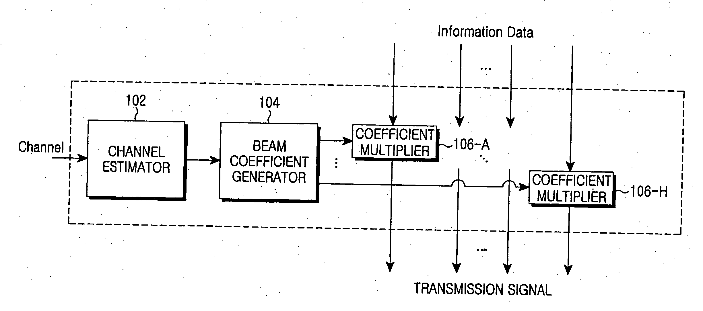
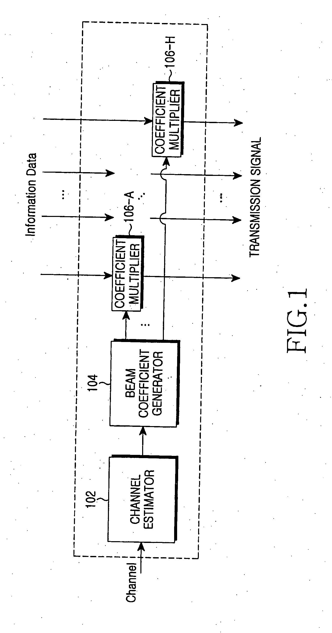
[0019] According to the present invention, a Base Station (BS) forms a beam in units of at least one sub-carrier to transmit a downlink signal to a Mobile Station (MS) in a wireless communication system. To this end, the present invention provides a new beam cell planning method capable of improving a Carrier-to-Interference ratio (C / I). Here, a unit of at least one sub-carrier may be a tile of bin used in an Institute of Electrical and Electronics Engineers (IEEE) 802.16 communication system. The tile or bin indicates a resource allocation unit...


PUM


Abstract

An apparatus and a method for transmitting a signal in a wireless communication system are disclosed. A method for transmitting a signal by a Base Station (BS) in a wireless communication system includes estimating an uplink channel using a signal received from a Mobile Station (MS), determining a beam coefficient for each of sub-carriers constituting a predetermined frequency band based on the estimated uplink channel, forming a beam for the predetermined frequency band by multiplying each sub-carrier by the beam coefficient, and transmitting a signal using the formed beam.

Description

PRIORITY [0001] This application claims priority under 35 U.S.C. § 119(a) of a Korean Patent Application filed in the Korean Intellectual Property Office on Feb. 20, 2006 and assigned Serial No. 2006-16284, the contents of which are incorporated herein by reference. BACKGROUND OF THE INVENTION [0002] 1. Field of the Invention [0003] The present invention relates generally to a wireless communication system, and in particular, to an apparatus and method for transmitting a signal to improve signal reception performance. [0004] 2. Description of the Related Art [0005] A smart antenna technology is designed to improve the performance of a transmitter or a receiver by using a plurality of antennas in the transmitter or the receiver in a wireless communication system. A Base Station (BS) provides a separate beam to each Mobile Station (MS) in a cell using a smart antenna. In other words, the BS forms a beam towards a destination MS in such a manner as to maximize a gain and forms a beam t...

Claims


Application Information

Patent Timeline
IPC IPC(8): H04M1/00
CPCH04W16/28G01N21/89G01N2021/845G01N2201/0415H01L21/67288H01L22/24
Inventor SUNG, SANG-HOONKIM, YONG-SEOKKWON, YOUNG-HOON
Owner SAMSUNG ELECTRONICS CO LTD
Why Eureka
Try Eureka