Al technical title is built by PatSnap Al team. It summarizes the technical point description of the patent document.
a prosthetic foot and tunable technology, applied in the field of high-performance prosthetic feet, can solve the problems of limited dynamic response characteristics of this known artificial foot, and achieve the effects of improving applied mechanics, high performance, and high performan
Inactive Publication Date: 2007-09-13
BIOQUEST PROSTHETICS
View PDF99 Cites 17 Cited by
Summary
Abstract
Description
Claims
Application Information
AI Technical Summary
This helps you quickly interpret patents by identifying the three key elements:
Problems solved by technology
Method used
Benefits of technology
[0011] In order to allow the amputee to attain a higher level of performance, there is a need for a high function prosthetic foot having improved applied mechanics, which foot can out perform the human foot and also out perform the prior art prosthetic feet. It is of interest t
Problems solved by technology
However, the dynamic response characteristic
Method used
Image
Click on the blue label to locate the original text in one second.
Reading with bidirectional positioning of images and text.
Examples
Embodiment Construction
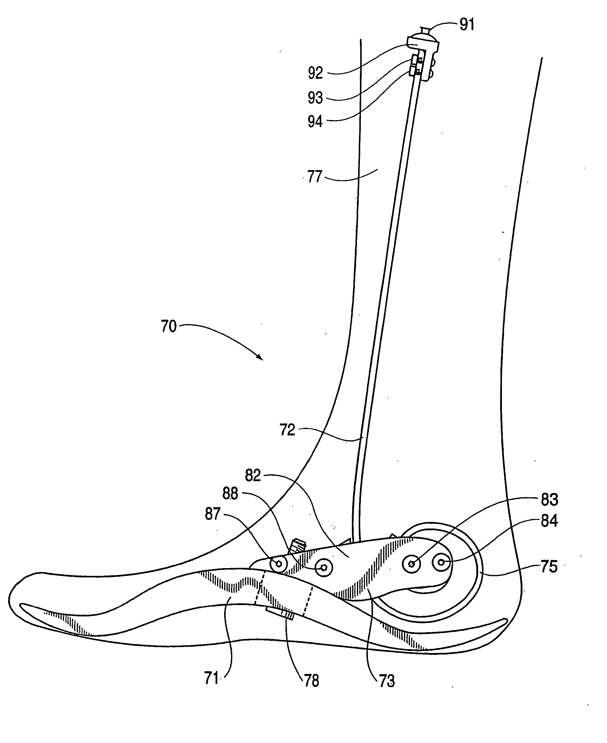
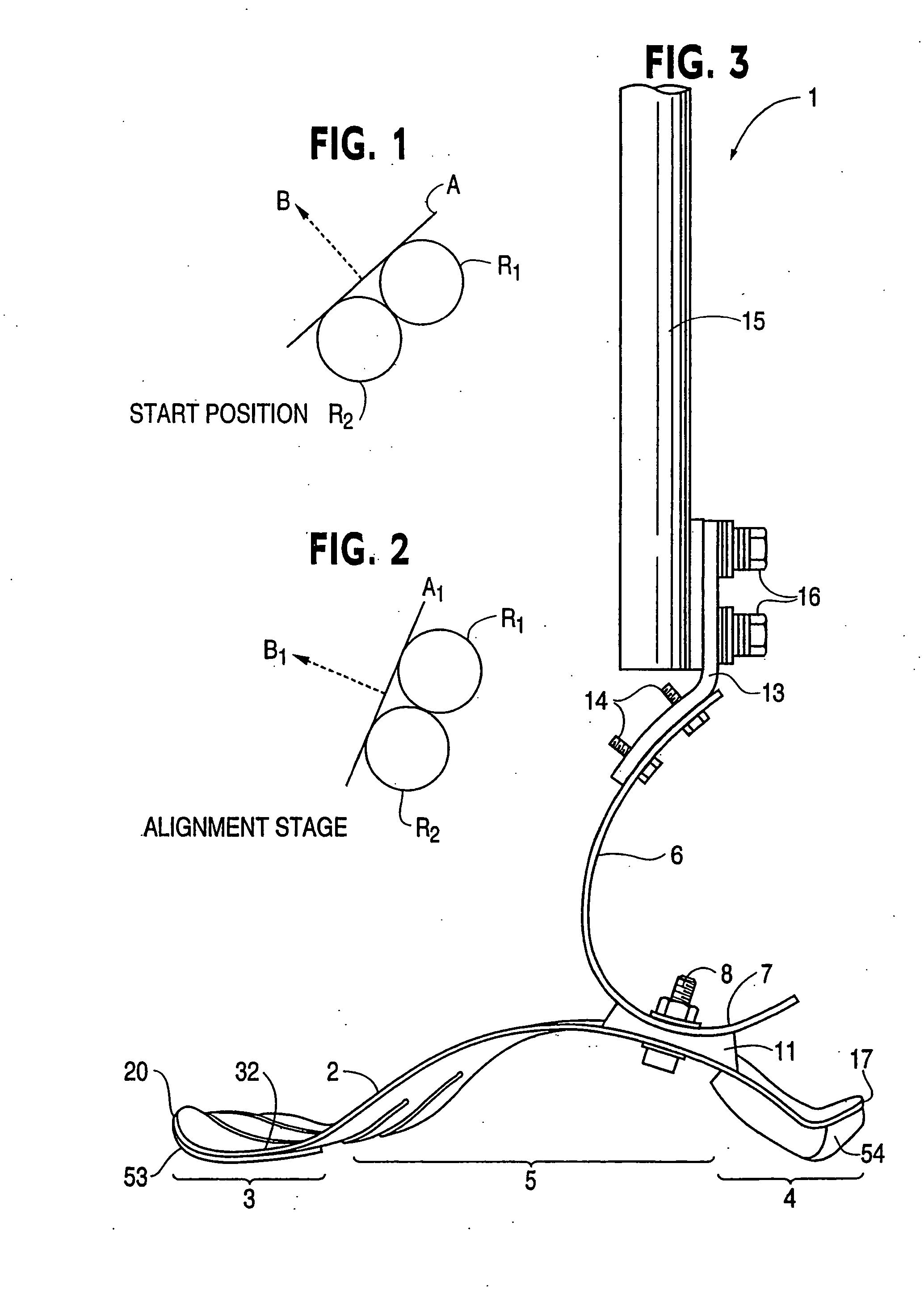
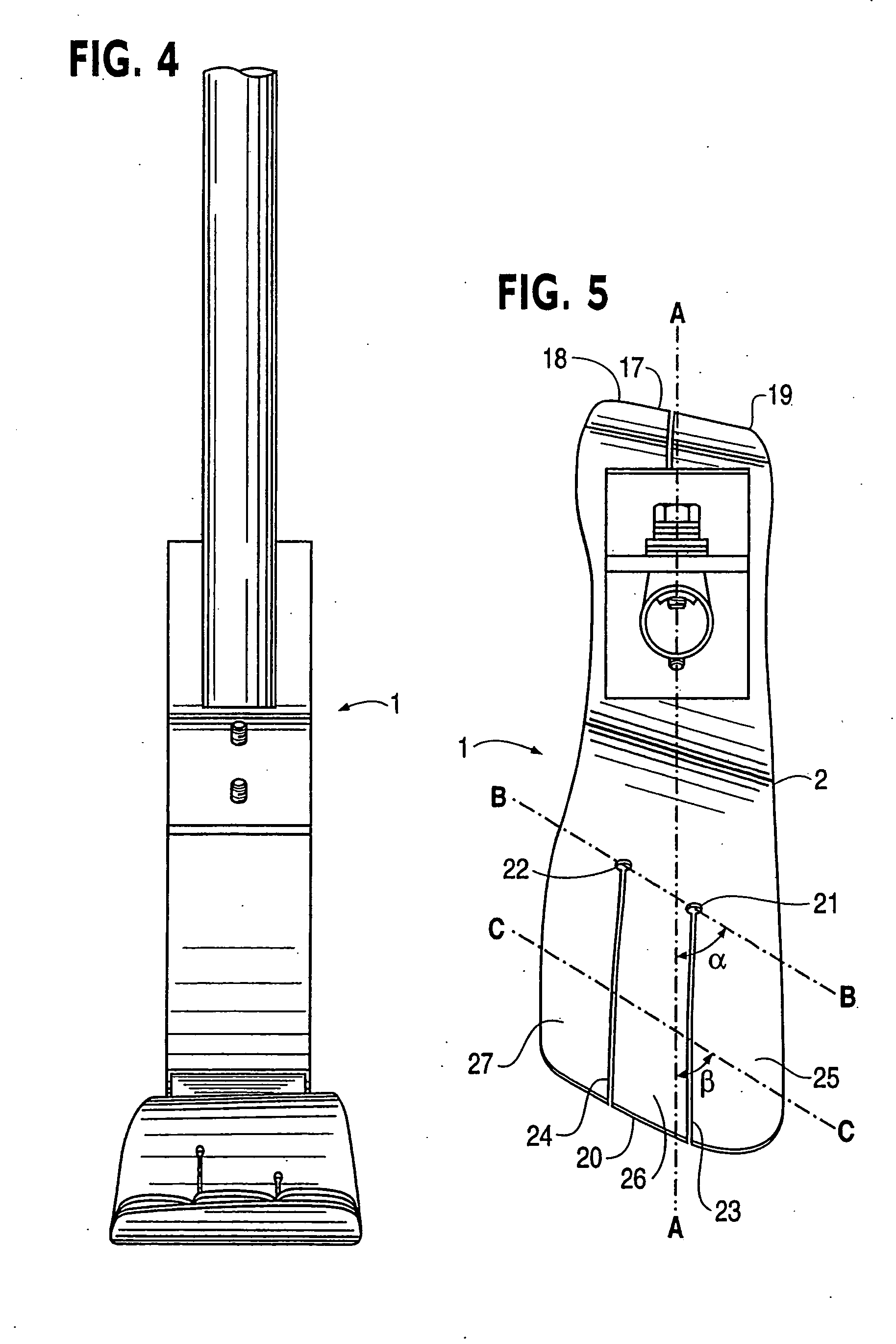
[0075] Referring now to the drawings, a prosthetic foot 1 in the example embodiment of FIGS. 3-5 is seen to comprise a longitudinally extending foot keel 2 having a forefoot portion 3 at one end, a hindfoot portion 4 at an opposite end and an upwardly arched midfoot portion 5 extending between the forefoot and hindfoot portions. The midfoot portion 5 is upward convexly curved over its entire longitudinal extent between the forefoot and hindfoot portions in the example embodiment.
[0076] An upstanding calf shank 6 of the foot 1 is attached at a portion of a downward convexly curved lower end 7 thereof to a proximate, posterior surface of the keel midfoot portion 5 by way of a releasable fastener 8 and coupling element 11. The fastener 8 is a single bolt with nut and washers in the example embodiment, but could be a releasable clamp or other fastener for securely positioning and retaining the calf shank on the foot keel when the fastener is tightened.
[0077] A longitudinally extending...
PUM
Abstract
A lower extremity prosthesis including a foot, an ankle, a shank and a posterior calf device to store energy during force loading of the prosthesis and return the stored energy during force unloading to increase the kinetic power generated for propulsive force by the prosthesis in gait. The posterior calf device includes at least one coiled spring formed monolithically with the shank and having a free end, and at least one elongated member extending between the free end of the at least coiled spring and the lower portion of the prosthesis. The at least one coiled spring is resiliently uncoiled in response to anterior movement of the upper end of the shank in gait for storing energy.
Description
RELATED APPLICATIONS′[0001] This application is a continuation in part of: [0002] (1) U.S. application Ser. No. 10 / 594,798 entered Sep. 29, 2006 as the U.S. national phase under 35 U.S.C. §371 of international application no. PCT / US2005 / 011291 filed Apr. 1, 2005; [0003] (2) U.S. application Ser. No. 10 / 814,260 filed Apr. 1, 2006; [0004] (3) U.S. application Ser. No. 10 / 594,796 entered Sep. 29, 2006 as the U.S. national phase of international application no. PCT / US2005 / 11292 filed Apr. 1, 2005, claiming priority of U.S. provisional application Ser. No. 60 / 558,119 filed Apr. 1, 2004; [0005] (4) U.S. application Ser. No. 10 / 814,155 filed Apr. 1, 2004; [0006] (5) U.S. application Ser. No. 10 / 473,682 filed Mar. 29, 2002, which is a continuation in part of U.S. application Ser. No. 09 / 820,895 filed Mar. 30, 2001, now U.S. Pat. No. 6,562,075 issued May 13, 2003; and [0007] (6) U.S. application Ser. No. 11 / 411,133 filed Apr. 26, 2006.TECHNICAL FIELD [0008] The present invention relates to a...
Claims
Application Information
Patent Timeline
Application Date:The date an application was filed.
Publication Date:The date a patent or application was officially published.
First Publication Date:The earliest publication date of a patent with the same application number.
Issue Date:Publication date of the patent grant document.
PCT Entry Date:The Entry date of PCT National Phase.
Estimated Expiry Date:The statutory expiry date of a patent right according to the Patent Law, and it is the longest term of protection that the patent right can achieve without the termination of the patent right due to other reasons(Term extension factor has been taken into account ).
Invalid Date:Actual expiry date is based on effective date or publication date of legal transaction data of invalid patent.