
Vehicle headway maintenance assist system and method

a technology for maintenance assistance and vehicles, applied in vehicle position/course/altitude control, braking system, instruments, etc., can solve problems such as limits imposed on the operation of deceleration control and cancellation of headway distance control

Active Publication Date: 2007-09-13
NISSAN MOTOR CO LTD +1
View PDF4 Cites 49 Cited by
  • Summary
  • Abstract
  • Description
  • Claims
  • Application Information

AI Technical Summary

Benefits of technology

[0007]It has been discovered that in conventional headway maintenance assist systems, headway distance control is canceled when the driver operates the accelerator, and headway distance control is idle while the accelerator is being operated. Therefore, sometimes a problem is encountered in that limits are imposed on the operation of deceleration control for maintaining headway distance.

Problems solved by technology

It has been discovered that in conventional headway maintenance assist systems, headway distance control is canceled when the driver operates the accelerator, and headway distance control is idle while the accelerator is being operated.
Therefore, sometimes a problem is encountered in that limits are imposed on the operation of deceleration control for maintaining headway distance.

Method used


Image

  • Vehicle headway maintenance assist system and method
  • Vehicle headway maintenance assist system and method
  • Vehicle headway maintenance assist system and method

Examples


first embodiment

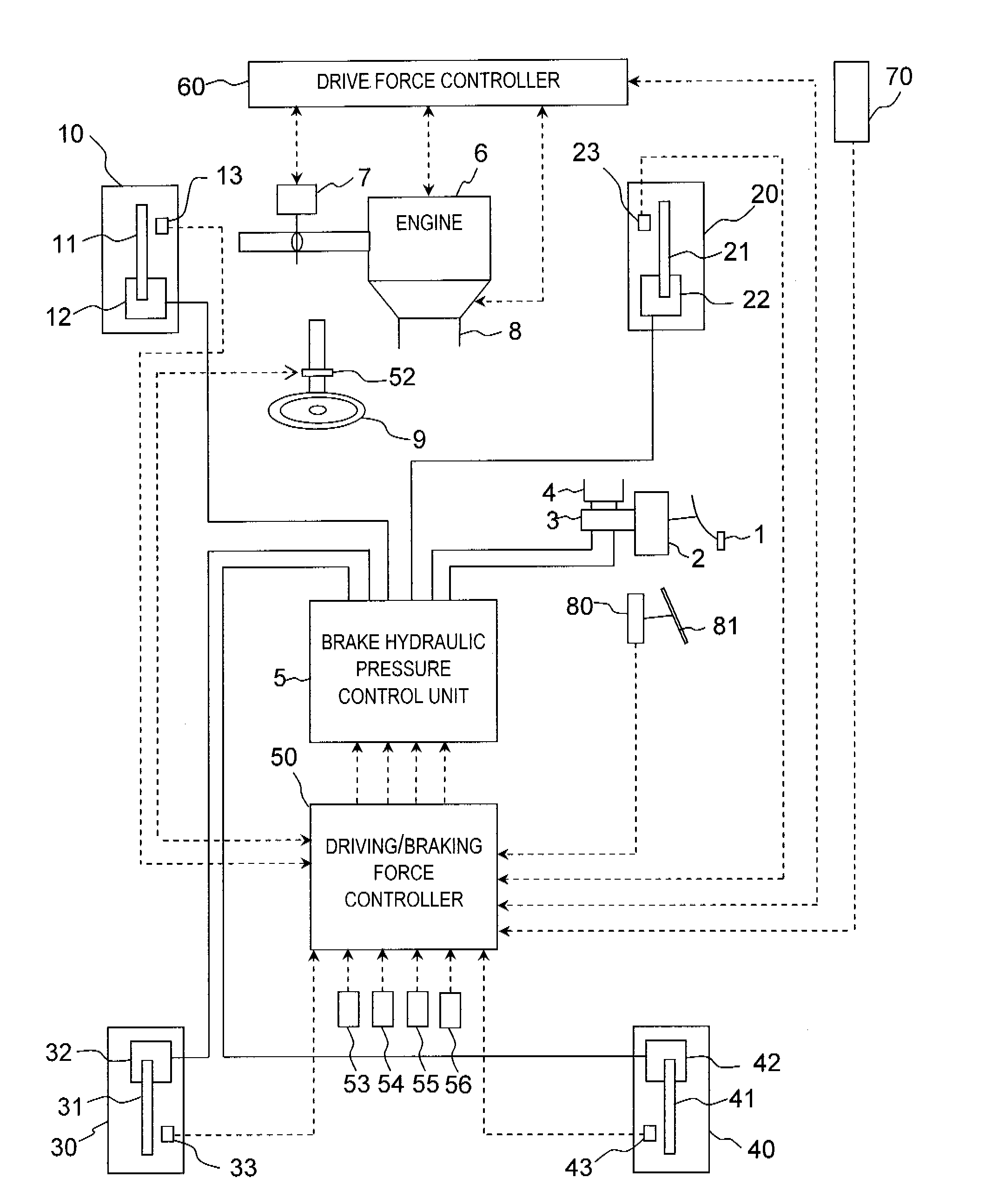
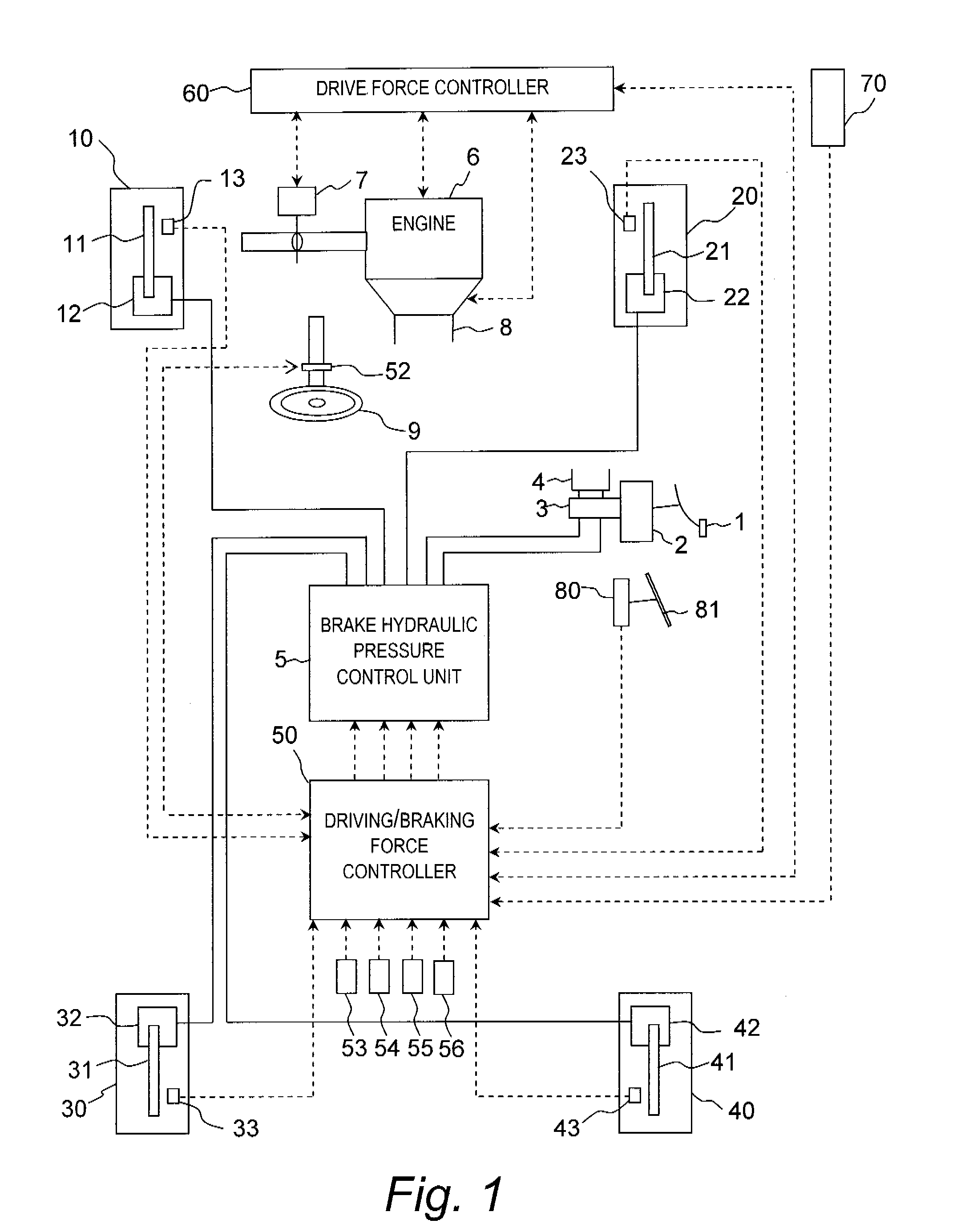
[0025]Referring initially to FIG. 1, a vehicle (hereinafter also called “the host vehicle”) is schematically illustrated with a vehicle headway maintenance assist system in accordance with the present invention. In this illustrated embodiment, the headway maintenance assist system is installed in the host vehicle that is a rear-wheel drive vehicle having an automatic transmission and a conventional differential gear. The host vehicle includes a hydraulic braking apparatus that uses a brake pedal 1, a booster 2, a master cylinder 3, a reservoir 4 and a pressure control unit 5 for the driver to input a target braking force to a left front wheel 10 via a brake disk 11 and a wheel cylinders 12, a right front wheel 20 via a brake disk 21 and a wheel cylinders 22, a left rear wheel 30 via a brake disk 31 and a wheel cylinders 32, and a right rear wheel 40 via a brake disk 41 and a wheel cylinders 42. In this host vehicle, the front wheels 10 and 20 and the rear wheels 30 and 40 are config...

second embodiment

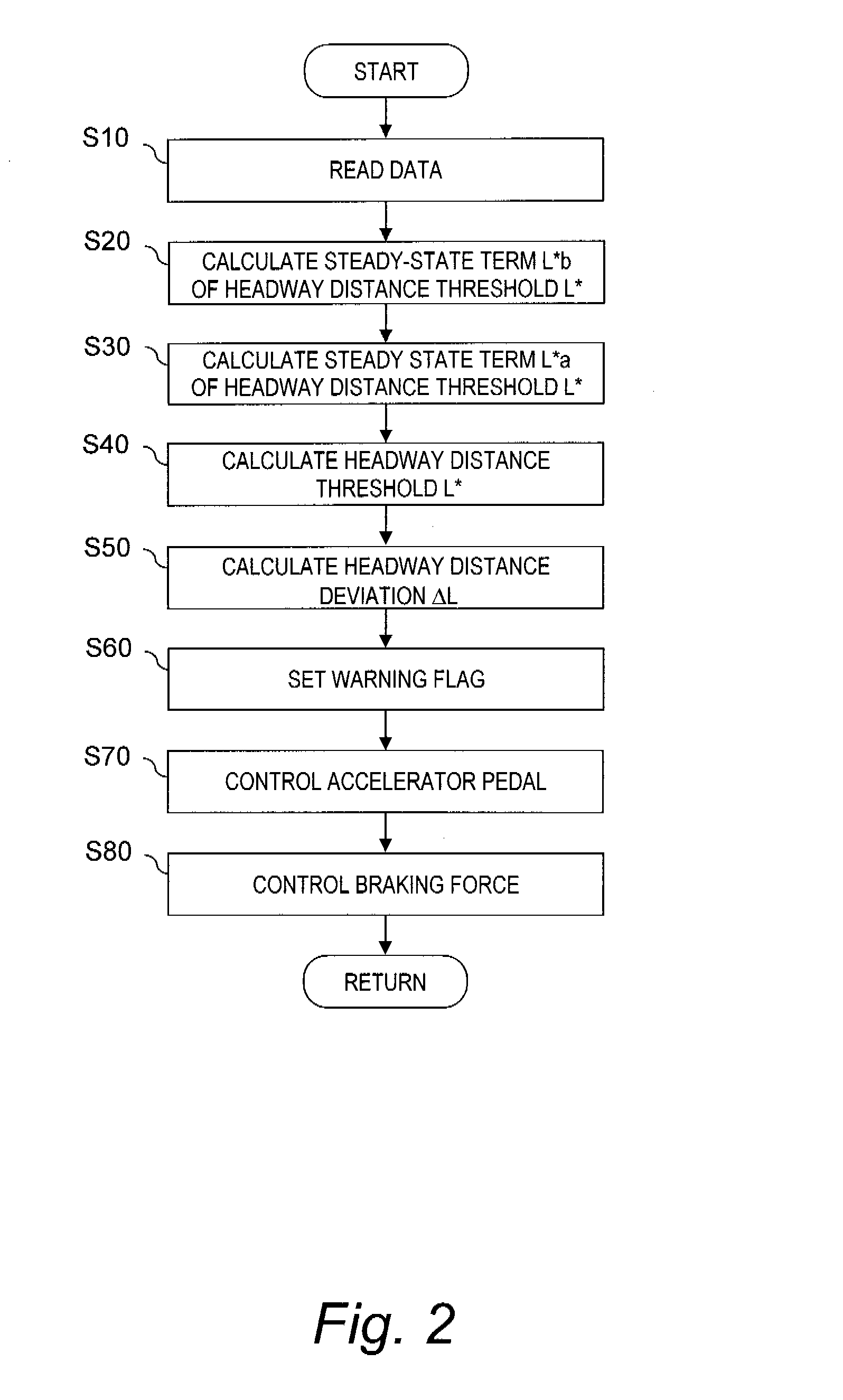
[0070]FIG. 7 is a flowchart showing the process performed by the headway maintenance assist system in the When the host vehicle is started up, the driving / braking force controller 50 initiates the process step S400. In step S400, the following data is read, e.g., the accelerator pedal position Acc detected by the accelerator pedal position sensor 56, the wheel speeds Vw1, Vw2, Vw3, Vw4 detected by the wheel speed sensors 13, 23, 33 and 43, and the headway distance L and the relative speed Vr with respect to the preceding vehicle as detected by the laser radar 70. The process then advances to step S410.

[0071]In step S410, the first headway distance threshold L*1 is calculated. The first headway distance threshold L*1 is calculated from the sum of a steady-state term L*h1, which does not depend on the running condition of the host vehicle, and a transient term L*r1, which depends on the running condition of the host vehicle. The specific method for calculating the first headway dista...


PUM


Abstract

A vehicle headway maintenance assist system is configured to perform a haptic notification control of an accelerator to prompt the driver to release the accelerator when the accelerator is being operated and to perform a deceleration control of the vehicle based on headway distance when the accelerator is being operated as long as the headway distance from a preceding vehicle is less than a prescribed headway distance threshold.

Description

CROSS-REFERENCE TO RELATED APPLICATIONS[0001]This application claims priority to Japanese Patent Application Nos. 2006-066546, filed on Mar. 10, 2006 and 2006-066366, filed on Mar. 10, 2006. The entire disclosures of Japanese Patent Application Nos. 2006-066546 and 2006-066366 are hereby incorporated herein by reference.BACKGROUND OF THE INVENTION[0002]1. Field of the Invention[0003]The present invention generally relates to a vehicle headway maintenance assist system for controlling the headway distance from a preceding vehicle. More specifically, the present invention relates to a vehicle headway maintenance assist system that perform deceleration control of the host vehicle when the headway distance is less than a prescribed headway distance threshold.[0004]2. Background Information[0005]Currently, vehicle headway maintenance assist systems have been proposed that apply a driving force and / or a braking force to a vehicle for controlling the headway distance from a host vehicle to...

Claims


Application Information

Patent Timeline
Patent Type & Authority Applications(United States)
IPC IPC(8): B60T7/12B60W10/18B60W30/16B60W40/10B60W50/08
CPCB60K26/021B60T7/22B60T2201/02B60W10/06B60W2550/308B60W30/16B60W40/105B60W50/16B60W2550/302B60W10/184B60W2554/804B60W2554/801B60W2554/4042B60W2540/10B60W2720/10B60W2754/30B60Y2300/16
Inventor TANGE, SATOSHIEGAWA, KENICHIKOBAYASHI, YOSUKE
Owner NISSAN MOTOR CO LTD
Learn More