
Headway control system

a control system and headway technology, applied in the direction of distance measurement, pedestrian/occupant safety arrangement, instruments, etc., can solve the problems of affecting the driving experience of drivers, difficult to establish a relationship between the stroke of the accelerator pedal and the on/off position of the switch, and the difficulty of setting the amount of depressed accelerator pedal to determine the actuation of the switch

Inactive Publication Date: 2005-04-05
HITACHI ASTEMO LTD
View PDF12 Cites 17 Cited by
  • Summary
  • Abstract
  • Description
  • Claims
  • Application Information

AI Technical Summary

Benefits of technology

It is an object of the present invention to provide a headway control system that is capable of starting a traffic congestion processing using the same operation as an ordinary driving operation.

Problems solved by technology

The manually operated switch, however, means that it necessary to provide a new switch.
Moreover, it requires that the driver perform an operation in addition to driving the vehicle, which bothers the driver.
With the prior art, in which the accelerator pedal is used as the switch, it is difficult to set how much the accelerator pedal is to be depressed to determine that the switch is actuated.
That is, it is difficult to establish a relationship between an accelerator pedal stroke and ON / OFF position of the switch.
Even while the following processing device is being activated, the driver is likely to feel hesitant about depressing the accelerator pedal hard when he or she is afraid that doing that could jump the host vehicle forward.
It is thus difficult to set a large pedal stroke to cause the device to determine that the switch is turned ON.
This presents a new problem to the configuration using the accelerator pedal as the operation switch.

Method used


Image

  • Headway control system
  • Headway control system
  • Headway control system

Examples


first embodiment

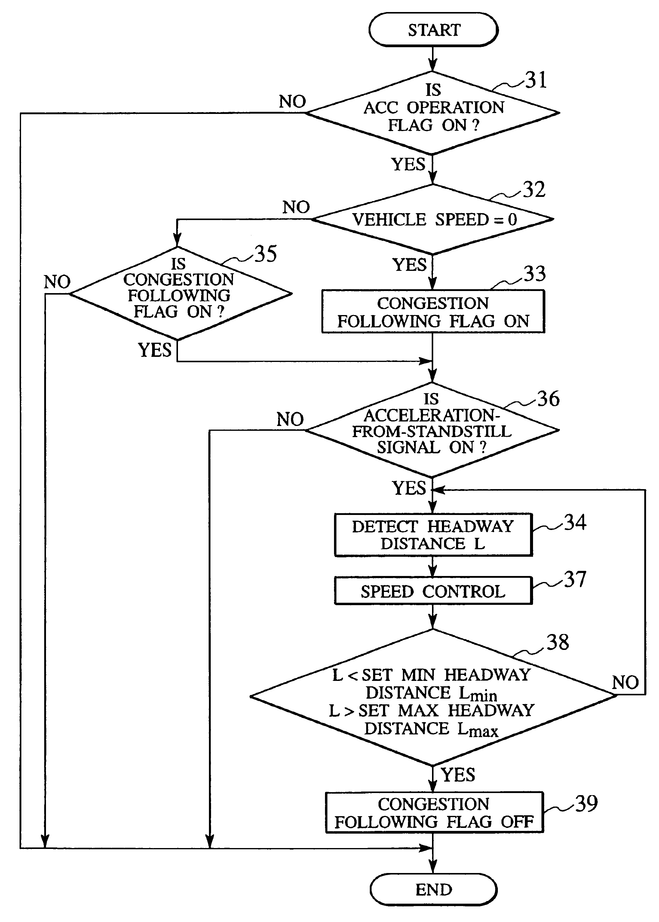
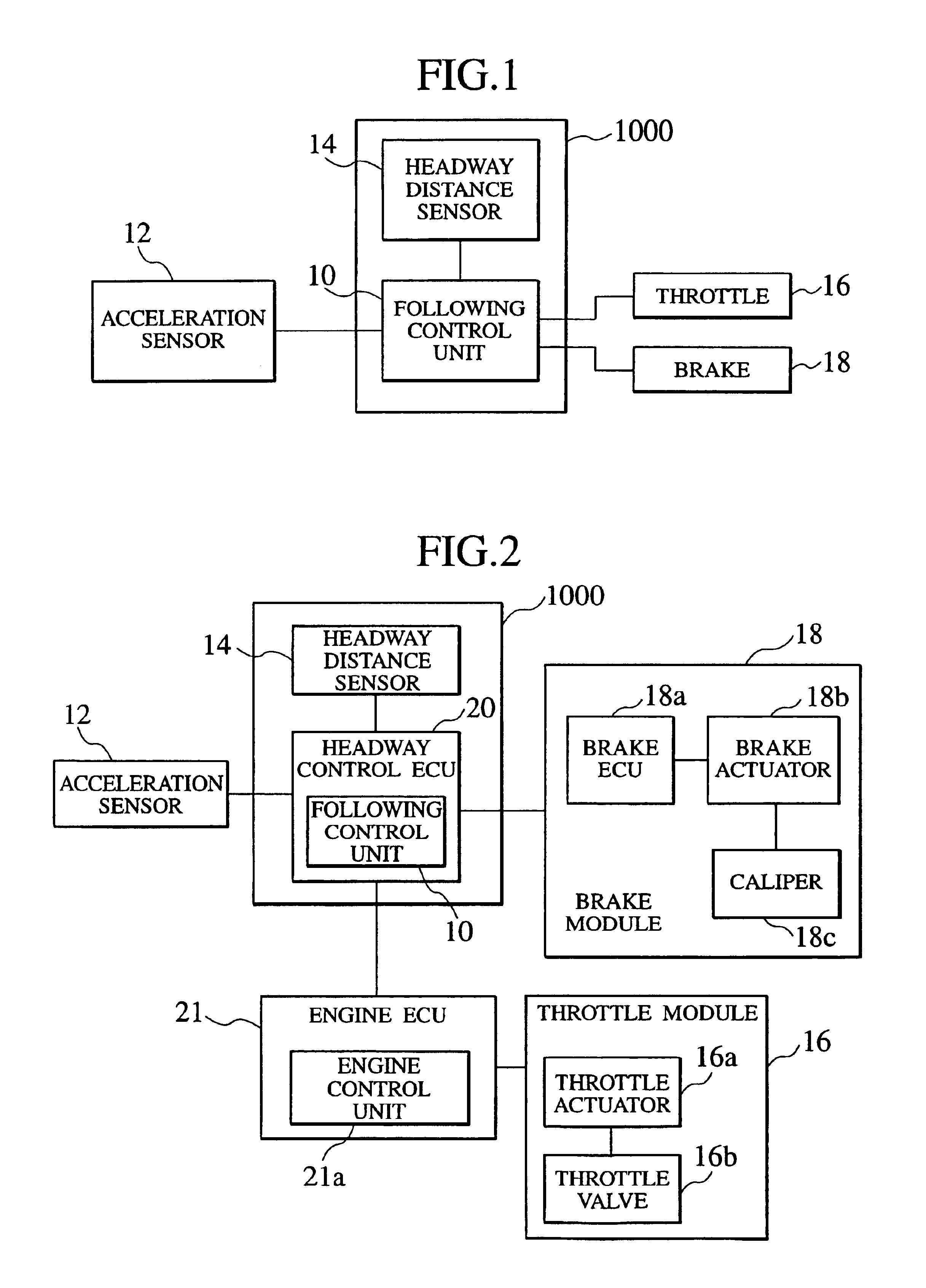
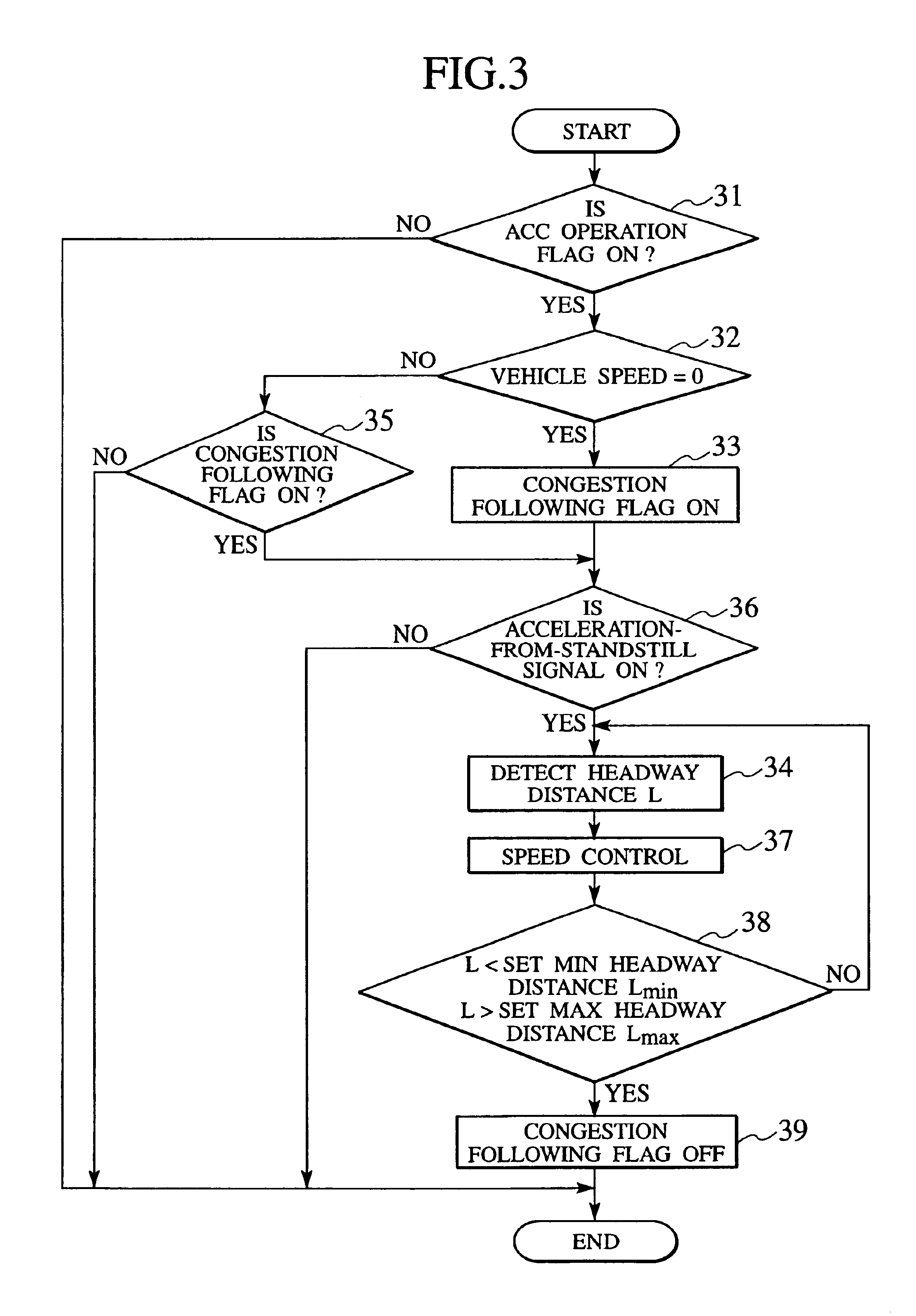
A headway control system 1000 provided with a traffic congestion following function according to a first embodiment of the present invention will be explained with reference to FIGS. 1 through 3. As shown in FIG. 1, the headway control system 1000 is provided with a following control unit 10 and a headway distance sensor 14. The following control unit 10 selects either a congestion stop mode or a congestion following mode, and performs a following processing when the congestion following mode is selected. The headway distance sensor 14 detects a headway distance from a preceding vehicle and a relative speed and outputs detected data to the following control unit 10. An acceleration sensor 12 provided in a vehicle is connected to the following control unit 10. The following control unit 10 is, on the other hand, connected to a throttle module 16 that adjusts an engine intake air amount and a brake module 18 that generates a braking force.

The acceleration sensor 12 detects acceleratio...

second embodiment

A headway control system 1100 provided with a traffic congestion following function according to a second embodiment of the present invention will be explained with reference to FIGS. 4 through 6.

The headway control system 1100 according to the second embodiment of the present invention is configured so as to perform the congestion following processing by detecting an engine positive pressure that builds up as the throttle valve opens when the vehicle is started. In the headway control system 1100 according to the second embodiment, therefore, the following control unit 10 is connected to an intake air pressure sensor 41 provided for the vehicle engine as shown in FIGS. 4 and 5. It is otherwise constructed in the same manner as the headway control system 1000 according to the first embodiment.

When the vehicle is started as the driver operates the accelerator pedal or any other switch, an intake air pressure that builds up as the throttle valve opens is detected by the intake air pre...

third embodiment

A headway control system 1200 provided with a traffic congestion following function according to a third embodiment of the present invention will be explained with reference to FIGS. 7 through 10.

The headway control system 1200 according to the third embodiment of the present invention is configured so as to set the congestion following mode by detecting an increase in an injection pulse width occurring as the vehicle is started. The headway control system 1200 according to the third embodiment therefore includes a pulse width counter 82 connected to the following control unit 10 as shown in FIGS. 7 and 8. The pulse width counter 82 is connected to an engine intake air sensor 81 provided for the vehicle engine.

When the host vehicle is started as the driver operates the accelerator pedal or any other switch, the injection pulse width increases with the increased fuel injection amount. The pulse width counter 82 obtains an injection reference pulse width through calculation using an a...


PUM


Abstract

To provide a headway control system, in which a congestion following processing can be started by the same operation as in ordinary driving. An arrangement is provided that lets a following control unit 10 to start a control to follow a preceding vehicle on condition that a characteristic value, which is produced in a host vehicle when a driver starts moving the host vehicle, is detected in congested traffic. Acceleration or a vehicle speed may be used as the characteristic value. Another possible arrangement is to start the following control on condition that a variation in an engine of the host vehicle, which is generated in the host vehicle when the driver operates to start moving the host vehicle, is detected in congested traffic. For example, the following control may be started under condition that at least either one of the following is detected: an increase in an engine speed, an increase in an intake pressure, an increase in an injection pulse width, an increase in an engine oil pressure, and an increase in the number of ignition pulses.

Description

BACKGROUND OF THE INVENTIONThe present invention relates to a headway control system and, more particularly, to a headway control system provided with a traffic congestion following processing function.A traffic congestion following device that allows a host vehicle to follow a preceding vehicle in heavy traffic is known. A common traffic congestion following device is provided with a function that detects a headway distance and a function that controls the host vehicle so as to move it forward or bring it to a stop. It performs a following processing to adjust the headway distance to an appropriate value. Two types of following processing are known. One is a fully automatic system, in which the host vehicle starts moving automatically as soon as the preceding vehicle moves forward. The other is a semi-automatic system that does not immediately perform the following processing even when the preceding vehicle moves forward, requiring intervention by a driver through switch operation ...

Claims


Application Information

Patent Timeline
Patent Type & Authority Patents(United States)
IPC IPC(8): B60K31/00B60R21/00F02D29/02G08G1/16
CPCB60K31/0008B60W30/16G08G1/16B60W2510/0623B60W2510/0638B60W2520/105B60W2540/12B60W2540/16B60W2510/0671G08G1/166B60W30/18027
Inventor KURAMOCHI, YUICHIMANAKA, TOSHIOADACHI, HIDEFUMI
Owner HITACHI ASTEMO LTD
Learn More