

Compliant embosser assembly
Active Publication Date: 2007-09-20
THE PROCTER & GAMBNE CO
View PDF23 Cites 3 Cited by
- Summary
- Abstract
- Description
- Claims
- Application Information
AI Technical Summary
Benefits of technology
[0045] Another advantage of the present invention is that a distance 375 (shown in FIG. 3B) between the embossing element 114 and the engaging surface 460 can be decreased versus conventional embossing processes. For example, in conventional embossing processes utilizing an all steel first roll, all steel embossing element, all steel first shaft, all steel second roll, all steel second shaft, and all steel hub, variations in the thickness of the wall 122 can cause pressure fluctuations. For example, a tube blank 120 having a wall 122 having a thickness of about 0.7 mm can experience higher pressures when engaged by the engaging region of the second roll when compared to a wall 122 having a thickness of about 0.5 mm. This higher pressure, in some instances, can be enough to cut through the material of the wall 122 thereby creating a defective part for an applicator. Consequently, the distance 375, in conventional embossing assemblies is typically greater than about 0.7 mm so that the number of tube blanks 120 which are cut through are reduced.
Problems solved by technology
Without the plunger tube, insertion of the tampon into the body can be difficult and / or problematic.
A problem with some conventional applicators is that the plunger tube can fall out of the insertion tube.
However, the threading of the removal string back through the plunger tube can be difficult because the removal string is generally not a rigid element.
In addition, some wearers may be reluctant to place the plunger tube back into the insertion tube after it has fallen out of the insertion tube.
Method used
View moreImage
Smart ImageViewing Examples

Examples
example
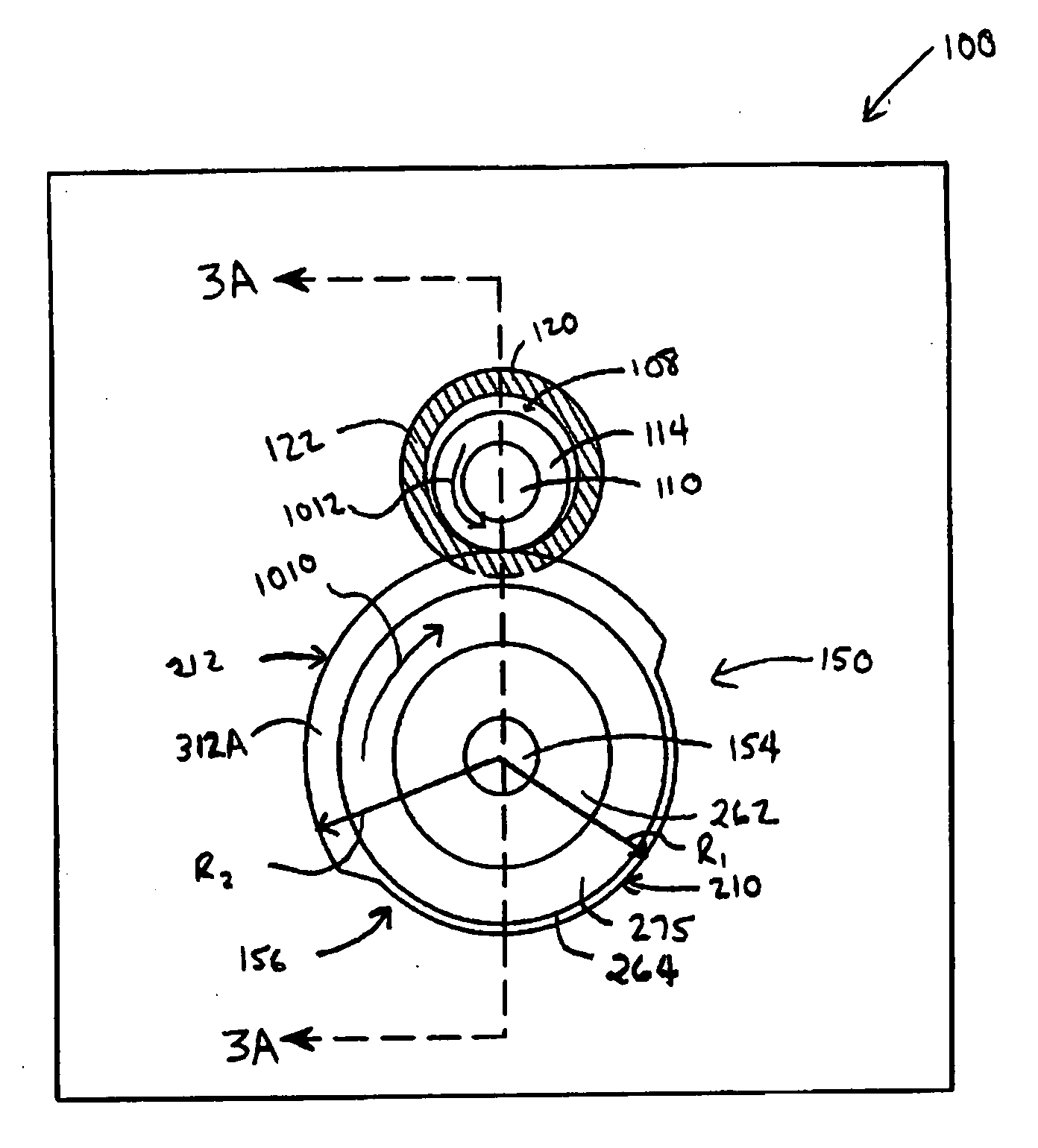
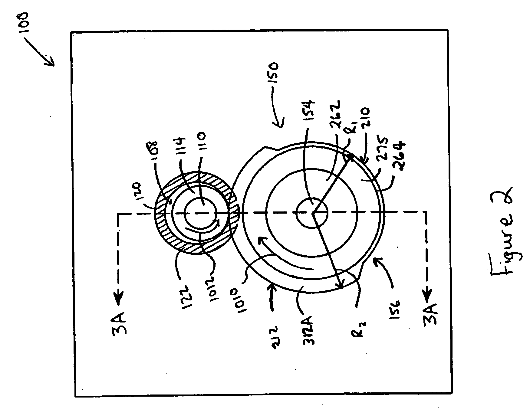
[0065] An exemplary second roll was created in accordance with the present invention. The anvil roll was configured similar to the anvil roll shown in FIG. 6. The compliant material 275 was disposed between the outer support 264 and the inner support 262. The compliant material 275 was applied at a thickness 610 of about 4.75 mm. The compliant material 275 had a durometer of 95 Shore A and was manufactured by Omni Technologies, Greenfield, Ind. The compliant material 275 was poured and formed through a compression mold.
Login to View More PUM
 Abstract
An embossing assembly for forming an embossment pattern on a tube blank having a first roll and a second roll. The first roll includes a first shaft having a first axis of rotation and an embossing element joined to the first shaft. The second roll is configured to engage a tube blank when the tube blank at partially surrounds the first roll. The second roll includes a second shaft and a hub joined to the second shaft. The hub includes an engagement region configured to apply pressure to a tube blank adjacent to the embossing element thereby causing part of the tube blank to at least partially conform to the shape of the embossing element. The engagement region includes a compliant material which is more compliant than the second shaft thereby allowing the engagement region to compensate for variations in a wall thickness of a tube blank.
Description
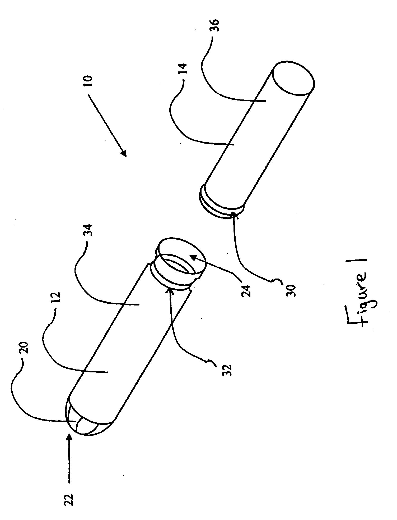
FIELD OF THE INVENTION [0001] This invention relates to an apparatus for embossing a pattern onto an applicator for disposable absorbent articles. More particularly, the present invention relates to an embosser assembly which may compensate for variations in material thickness, may reduce vibrations associated with the embossing assembly and may improve the embossing line process and / or embossing quality. BACKGROUND OF THE INVENTION [0002] Disposable absorbent articles utilized to absorb menses are well known. An example of such a disposable absorbent article which has gained much popularity is the disposable tampon. [0003] In order to facilitate the insertion of the tampon into the body, tampons are often packaged with a tampon applicator. In general, the applicator includes an insertion tube and a plunger tube which is telescopically associated with the insertion tube. The insertion tube typically comprises an insertion end and a removal end. The tampon is typically disposed in th...
Claims
Login to View More Application Information
Patent Timeline
 IPC IPC(8): B44B5/00
CPCA61F13/266A61F13/2085
InventorHOOK, JEREMY FREDERICBASHAM, JEREMY ROBERTKEIGHLEY, JAMES ARTHUR
OwnerTHE PROCTER & GAMBNE CO