Pneumatic Tire

a pneumatic tire and tire body technology, applied in the field of pneumatic tires, can solve the problems of low roadholding ability on dry road surfaces, drainage properties and roadholding ability to be decreased on wet road surfaces, and achieve the effect of high wet drainage performance and excellent

Inactive Publication Date: 2007-09-20
BRIDGESTONE CORP
View PDF8 Cites 33 Cited by
  • Summary
  • Abstract
  • Description
  • Claims
  • Application Information

AI Technical Summary

Benefits of technology

[0082] Because the pneumatic tire of the invention has the above configurations, the pneumatic tire has th...

Problems solved by technology

However, when the groove width or the groove depth is increased, a ground contact area is decreased on the dry road surface, and a shortage of rigidity may be cased in a land portion, which may result in lower roadholding ability on the dry road surface.
H...

Method used


Image

  • Pneumatic Tire
  • Pneumatic Tire
  • Pneumatic Tire

Examples


first embodiment

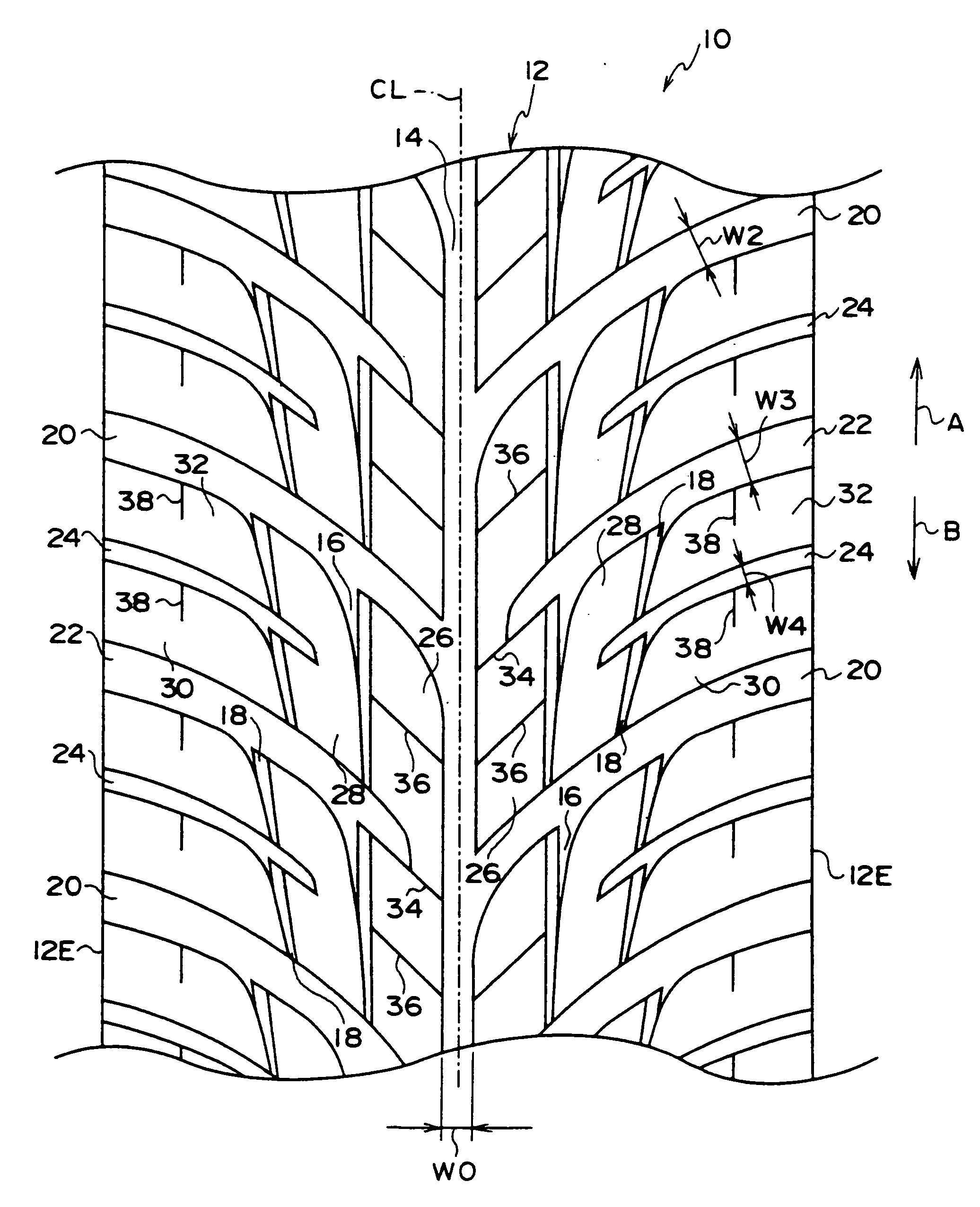
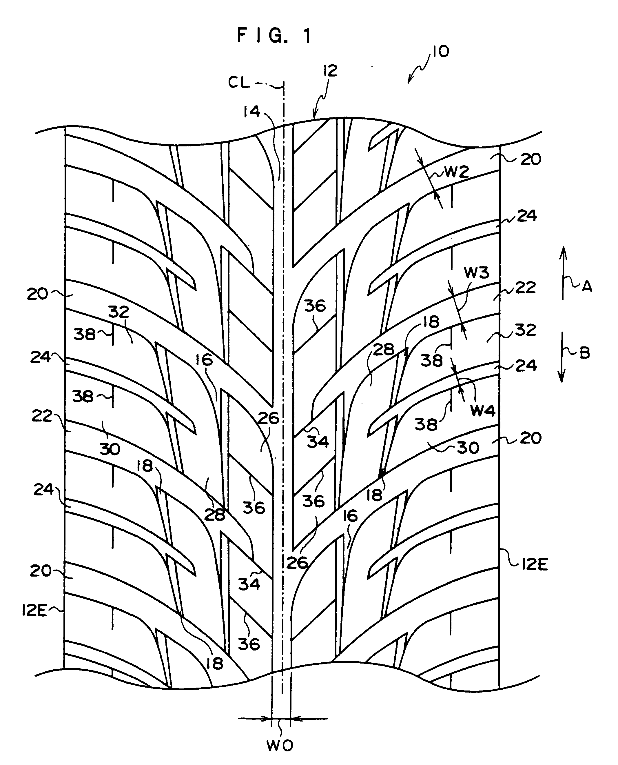
[0123] A first embodiment of a pneumatic tire of the invention will be described in detail with reference to the drawings.

[0124] As shown in FIG. 1, a circumferential wide major groove 14 is formed on a tire equatorial plane CL in a tread 12 of a pneumatic tire 10 of the first embodiment. The circumferential wide major groove 14 is linearly extended in a tire circumferential direction (directions of arrows A and B, the direction of arrow B is a tire rotating direction). First narrow circumferential minor grooves 16 extended in the tire circumferential direction are formed on the outside in a tire axis direction with respect to the circumferential wide major groove 14. Second narrow circumferential minor grooves 18 extended in the tire circumferential direction are further formed on the outside in the tire axis direction with respect to the first narrow circumferential minor grooves 16.

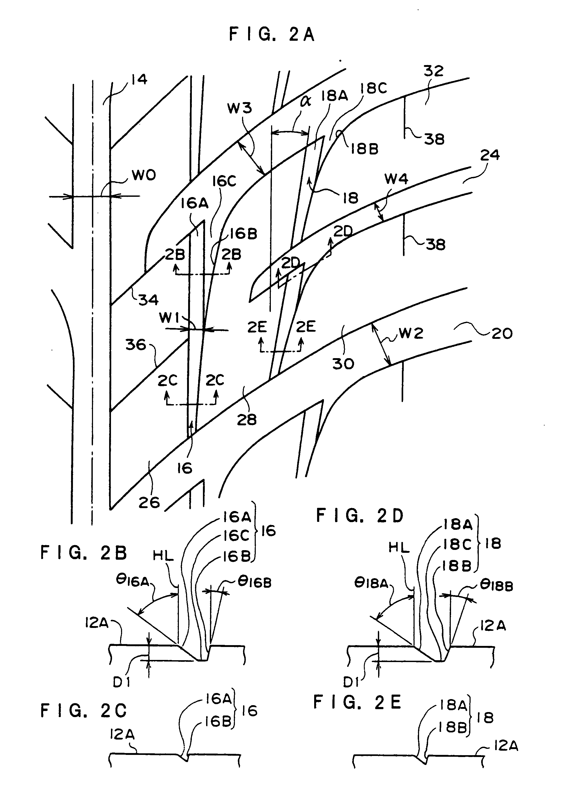
[0125] As shown in FIG. 2A, a groove wall 16A on the side of the tire equatorial plane CL of the ...

second embodiment

[0178] A second embodiment of a pneumatic tire of the invention will be described in detail with reference to the drawings.

[0179] As shown in FIG. 3, a circumferential wide major groove 114 is formed on the tire equatorial plane CL in a tread 112 of a pneumatic tire 110 of the second embodiment. The circumferential wide major groove 114 is linearly extended in the tire circumferential direction. First narrow circumferential minor grooves 116 extended in the tire circumferential direction are formed on the outside of the circumferential wide major groove 114 in a tire axis direction. Second narrow circumferential minor grooves 118 extended in the tire circumferential direction are further formed on the outside of the first narrow circumferential minor grooves 116 in the tire axis direction.

[0180] As shown in FIG. 4A, a groove wall 116A of the first narrow circumferential minor groove 116 that is provided at the tire equatorial plane CL side is linearly extended in the tire circumfe...

third embodiment

[0237] A third embodiment of a pneumatic tire of the invention will be described in detail with reference to the drawings.

[0238] As shown in FIG. 7, a pneumatic tire 210 according to the third embodiment includes a carcass 212. The carcass 212 includes cords which are substantially extended in the radial direction, and both end portions are folded by bead cores 211 respectively. The carcass 212 is formed by a single layer or multilayer.

[0239] A belt layer 214 in which plural belt plies are laminated is embedded on the outside in a tire radial direction of a crown portion 12C of the carcass 212. A tread portion 218 in which the grooves are arranged is formed on the outside in the tire radial direction of the belt layer 214.

[0240] As shown in FIG. 8A, in a wheel tread portion 219 of the tread portion 218, a first outer major groove 222A extended in the tire circumferential direction is formed on one surface side with respect to the tire equatorial plane CL, and a second outer major...


PUM


Abstract

The present invention provides a pneumatic tire which can obtain a high wet drainage performance, roadholding ability, and wear-resistant property without sacrificing other capabilities A directional pattern is formed by a circumferential wide major groove 14, a first narrow circumferential minor groove 16, a second narrow circumferential minor groove 18, a first transverse groove 20, a second transverse groove 22, and a third transverse groove 24. The circumferential wide major groove 14 is provided in a center region in a tire width direction of a tread 12. The first narrow circumferential minor groove 16 is arranged on the outside in a tire axis direction of the circumferential wide major groove 14. The second narrow circumferential minor groove 18 is arranged on the outside in the tire axis direction of the first narrow circumferential minor groove 16. The first transverse groove 20 is extended from a tread end 12E and coupled to the circumferential wide major groove 14. The second transverse groove 22 is arranged between the first transverse grooves 20, and the second transverse groove 22 is extended from the tread end 12E and terminated while not coupled to the circumferential wide major groove 14. The third transverse groove 24 is arranged between the first transverse groove 20 and the second transverse groove 22, and the third transverse groove 24 is extended from the tread end 12E and terminated between the first narrow circumferential minor groove 16 and the second narrow circumferential minor groove 18. Therefore, in wet road surface driving, the water between the pneumatic tire and a road surface flows efficiently into each groove to obtain high wet performance. Because the high wet performance is obtained while an increase in negative ratio is suppressed, a wheel tread area of a block is secured to improve a wear-resistant property. A circumferential length of a second block 28 becomes a substantial half of a first block 26, and circumferential lengths of a stepping-on side third block 30 and a kickout side third block 32 become a substantial half of the second block 28. Therefore, a wet drainage property can be improved on both sides of the tread while block rigidity is increased on a tread central region to improve traction performance, brake performance, and cornering performance. Furthermore, when the pneumatic tire of the invention is used in a front wheel, handling performance is improved by increasing the block rigidity in a central region in the tire axis direction. Widths and depths of the first narrow circumferential minor groove 16 and second narrow circumferential minor groove 18 are decreased from a kickout side toward a stepping-on side of the block in a range where the block is zoned by the first and second narrow circumferential minor grooves 16 and 18. Therefore, the block rigidity is increased on the stepping-on side of the blocks located on both sides of the first and second narrow circumferential minor grooves 16 and 18, and thereby the traction performance, brake performance, and cornering performance are improved.

Description

TECHNICAL FIELD [0001] The present invention relates to a pneumatic tire, particularly to the pneumatic tire which can obtain a high wet drainage property without sacrificing other capabilities. BACKGROUND ART [0002] In the pneumatic tire, a circumferential groove and a transverse groove are arranged in a tread to obtain wet performance (see Patent Documents 1 to 3). [0003] Conventionally, in the pneumatic tire, various devices are made to improve tire performance (for example, see Patent Documents 4 to 7). In order to improve the drainage on a wet road surface, a groove volume is increased by increasing a groove width or a groove depth. [0004] In a racing ultra-high performance vehicle tire, a technique of linearly arranging several circumferential grooves in a center region of the tread is taken to improve hydroplaning performance, and the technique increases a negative ratio. Patent Document 1: Japanese Patent Laid-Open No. 57-194106 (FIG. 2) Patent Document 2: Japanese Patent ...

Claims


Application Information

Patent Timeline
IPC IPC(8): B60C11/03B60C11/04B60C11/13
CPCB60C11/0302B60C11/0309B60C11/13B60C2011/0374B60C11/125B60C2011/0369Y10S152/03B60C11/1369
Inventor FUKUNAGA, TAKAYUKI
Owner BRIDGESTONE CORP
Why Eureka
Try Eureka