Mesh-type heat dissipating structure

Inactive Publication Date: 2007-09-20
INVENTEC CORP
View PDF6 Cites 9 Cited by
  • Summary
  • Abstract
  • Description
  • Claims
  • Application Information

AI Technical Summary

Benefits of technology

[0004] In light of the above drawbacks of the prior art, an objective of the present invention is to provide a heat dissipating structure to effectively increase the heat dissipating efficiency.
[0005] Another objective of the present invention is to provide a mesh-type heat dissipating structure having increased heat dissipating area and reduced weight.
[0007] In a preferred embodiment, the base is formed with a plurality of positioning grooves on a surface thereof, wherein the positioning grooves are arranged at intervals and in an oblique manner relative to edges of the surface of the base. The positioning grooves are formed of fixing members engaged with the base, the fixing members having recessed grooves, so as to allow the heat dissipating fins to be coupled to the fixing members and assembled to the base. By provision of the plurality of meshes of the heat dissipating fins, it can effectively overcome the drawbacks in the prior art, such as low degree of mixing of heat exchange between airflow and heat in an airflow path formed between fins, reduced airflow speed at a later part of the airflow path formed between the fins due to not providing kinetic energy supply for the airflow, insufficient heat dissipating area, and relatively heavier weight. Therefore, the heat dissipating structure of the present invention can increase the heat dissipating efficiency when the heat dissipating structure is applied in the electronic device.

Problems solved by technology

Such heat dissipating structure has significant drawbacks, for example, insufficient heat dissipating area, relatively heavier weight, and low degree of mixing of heat exchange between airflow and heat in an airflow path formed between the fins, thereby resulting in an unsatisfactory heat dissipating efficiency.
Moreover, the airflow in the airflow path formed between the fins does not have kinetic energy supply, making the airflow speed reduced at a later part of the airflow path and affecting the heat dissipating efficiency.
Therefore, the problem to be solved here is to provide a heat dissipating structure for effectively increasing the heat dissipating efficiency, which has a relatively lighter weight as compared with the conventional one made of the same material.

Method used


Image

  • Mesh-type heat dissipating structure
  • Mesh-type heat dissipating structure

Examples


Embodiment Construction

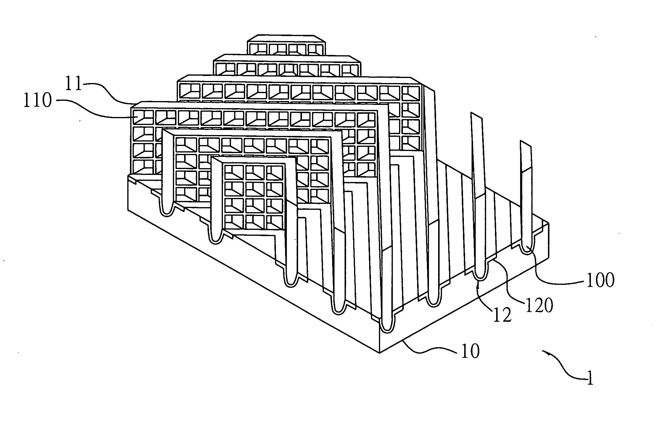
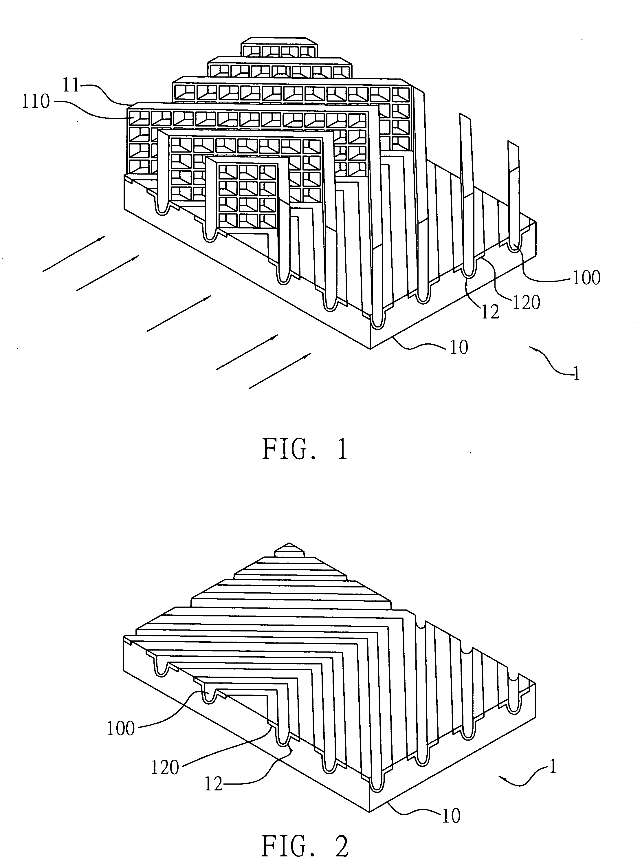
[0011] The preferred embodiment of a mesh-type heat dissipating structure proposed in the present invention is described as follows with reference to FIGS. 1 and 2. It is to be noted that the drawings are simplified schematic diagrams and only show components relating to the present invention. In practice, the layout of components could be more complicated. It should be understood that the following embodiment is not construed to limit the scope of the present invention.

[0012] As shown in FIGS. 1 and 2, a mesh-type heat dissipating structure 1 of the present invention comprises a base 10 and a plurality of heat dissipating fins 11 vertically disposed at intervals on the base 10, wherein each of the heat dissipating fins 11 has a plurality of meshes 110.

[0013] The base 10 has a plurality of positioning grooves 100 on a surface thereof, for positioning the heat dissipating fins 11. The positioning grooves 100 are arranged at intervals and in an oblique manner relative to edges of th...


PUM


Abstract

A mesh-type heat dissipating structure includes a base and a plurality of heat dissipating fins disposed at intervals on the base, each of the heat dissipating fins having a plurality of meshes to increase the heat dissipating area of the heat dissipating structure, such that the mesh-type heat dissipating structure can increase the heat dissipating efficiency effectively.

Description

FIELD OF THE INVENTION [0001] The present invention relates to heat dissipating structures, and more particularly, to a heat dissipating structure applied in an electronic device to dissipate heat. BACKGROUND OF THE INVENTION [0002] A conventional heat dissipating structure provided in a desktop computer or a laptop computer normally comprises a base and a plurality of rectangular fins disposed on the base, and mostly the base and the fins are integrally formed. Such heat dissipating structure has significant drawbacks, for example, insufficient heat dissipating area, relatively heavier weight, and low degree of mixing of heat exchange between airflow and heat in an airflow path formed between the fins, thereby resulting in an unsatisfactory heat dissipating efficiency. Moreover, the airflow in the airflow path formed between the fins does not have kinetic energy supply, making the airflow speed reduced at a later part of the airflow path and affecting the heat dissipating efficienc...

Claims


Application Information

Patent Timeline
IPC IPC(8): H05K7/20
CPCG06F1/20H01L23/367H01L23/467H01L2924/0002H01L2924/00
Inventor HSU, I-CHE
Owner INVENTEC CORP
Why Eureka
Try Eureka