
Cover support mechanism and image forming apparatus incorporating the same

a technology of image forming apparatus and support mechanism, which is applied in the direction of ovens, instruments, ovens, etc., can solve the problems of difficult and the occurrence of obstacles to the operation of the electronic device, etc., and achieve the effect of easy transmission of weight of the cover

Active Publication Date: 2007-09-20
SHARP KK
View PDF2 Cites 9 Cited by
  • Summary
  • Abstract
  • Description
  • Claims
  • Application Information

AI Technical Summary

Benefits of technology

[0014]Furthermore, the support unit also has a braking unit which applies frictional force to the stopper when the cover is opened. When the braking unit applies frictional force to the stopper, it becomes easy to keep the wire stationary, and as a result it becomes easy for the cover to be kept stationary while it is open. Furthermore the biasing member can easily last over the long term, since the weight of the cover cannot easily be transmitted to the biasing member.
[0015]It should be understood that it is desirable for the receiving portion to be constituted as a long and narrow passage which slopes down towards the interior of the electronic device. The reason is that, in this case, the stopper which supports the opened cover is bent around the braking unit, so that the braking unit easily applies its frictional force to the stopper.

Problems solved by technology

As a result, it becomes unlikely that obstacles to the operation of the electronic device arise due to the portion of the stopper which is slack sticking out from the chassis, or contacting components of the electronic device.

Method used


Image

  • Cover support mechanism and image forming apparatus incorporating the same
  • Cover support mechanism and image forming apparatus incorporating the same
  • Cover support mechanism and image forming apparatus incorporating the same

Examples


Embodiment Construction

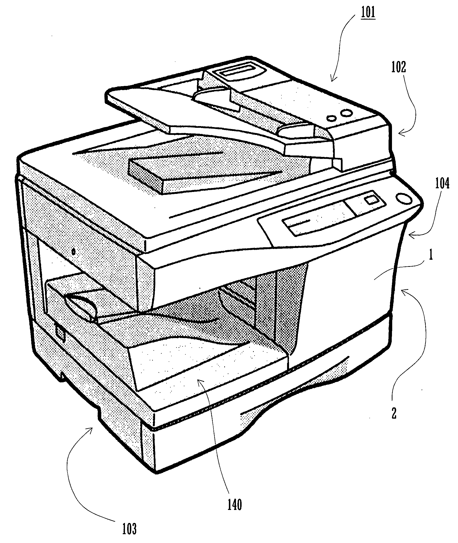
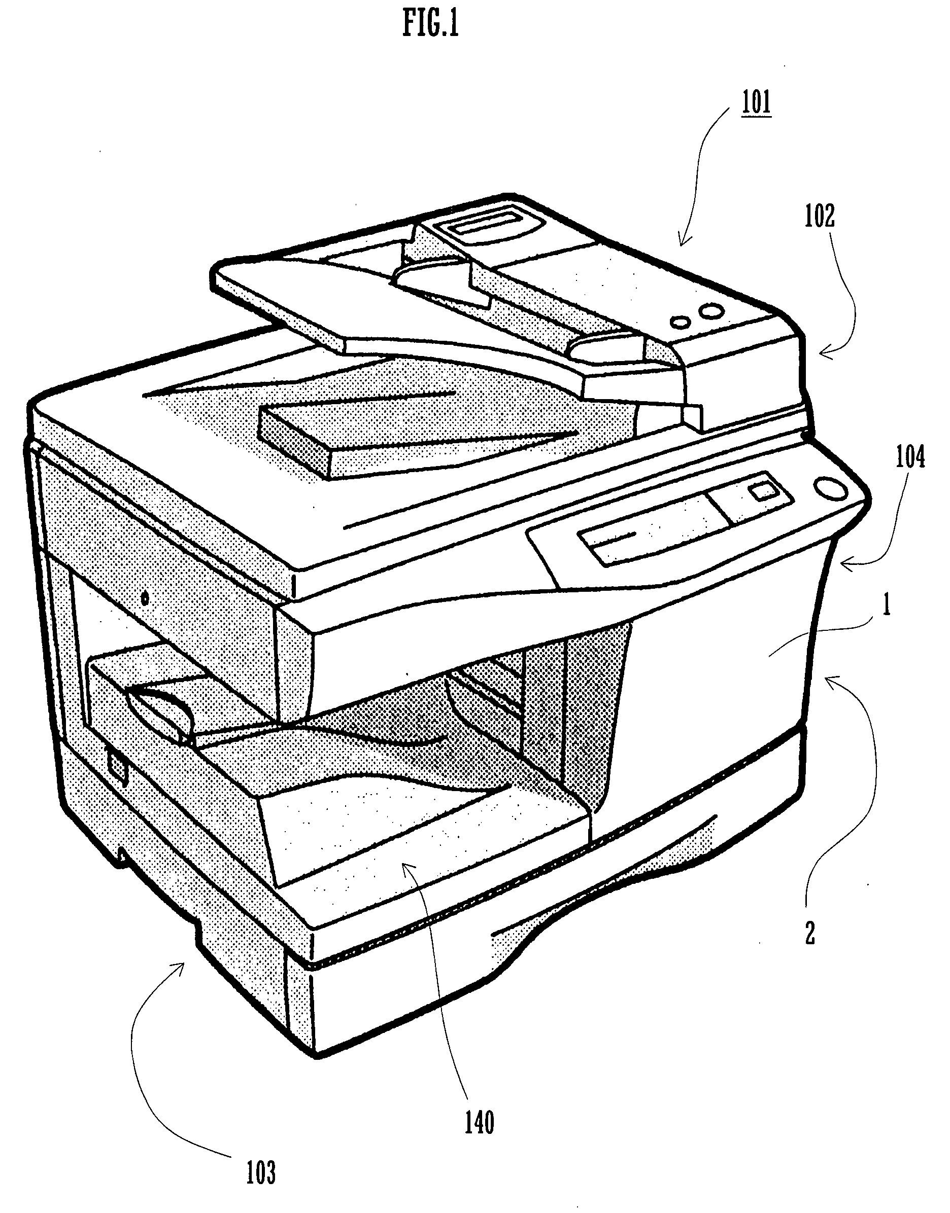
[0022]As shown in FIG. 1, an image forming apparatus 101 comprises a document reading unit 102, a paper supply unit 103, an image forming unit 104, and a paper delivery unit 140. Furthermore, the image forming apparatus 101 comprises a chassis 2 which covers over the document reading unit 102, the paper supply unit 103, and the image forming unit 104. This chassis 2 comprises a front surface cover which opens and closes freely. The present invention relates to a cover support mechanism for supporting this front surface cover 1, and the details thereof will be described hereinafter.

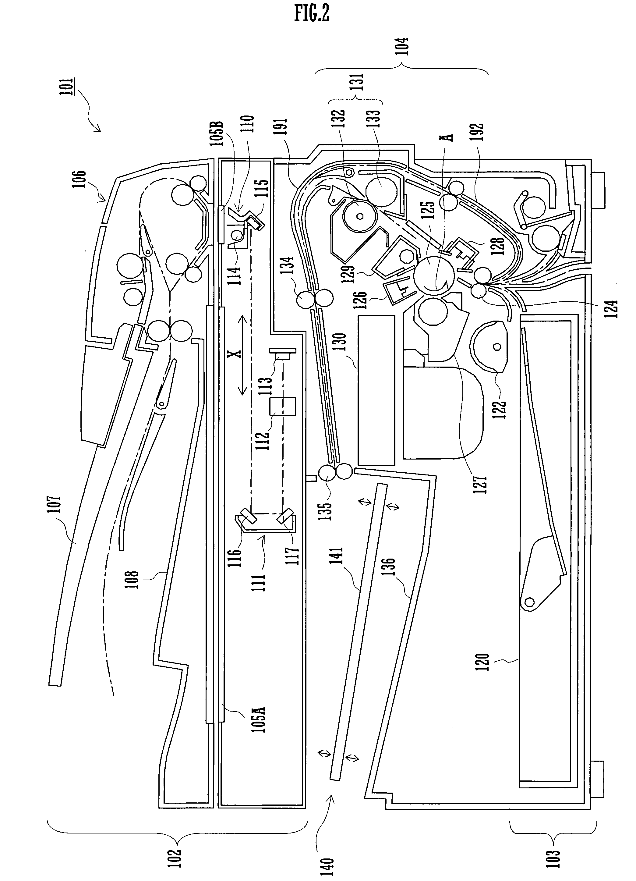
[0023]The structure of this image forming apparatus 101 will now be explained in a simple manner using FIGS. 1 and 2. The document reading unit 102 is disposed at the upper portion of the image forming apparatus 101. On the other hand, the paper supply unit 103 is disposed at the bottom portion of the image forming apparatus 101. And the image forming unit 104 is disposed so as to be sandwiched between the...


PUM


Abstract

A cover support mechanism regulates an opening angle of an openable cover with respect to a chassis of an electronic device. The cover constitutes a portion of the chassis. The mechanism has a cord shaped or tape shaped stopper, and a support unit. The stopper has a first end portion and a second end portion, the first end portion being fixed to the cover. The support unit supports the second end portion of the stopper. The support unit is provided to the electronic device. The support unit has a receiving portion, a biasing member, and a braking unit. The receiving portion has a space for pulling in the second end portion of the stopper. The biasing member applies force to the stopper for pulling in the stopper into the receiving portion. The braking unit applies frictional force to the stopper when the cover is opened.

Description

CROSS REFERENCE[0001]This Nonprovisional application claims priority under 35 U.S.C. § 119(a) on Patent Application No. 2006-071254 filed in Japan on Mar. 15, 2006, the entire contents of which are hereby incorporated by reference.BACKGROUND OF THE INVENTION[0002]The present invention relates to a cover support mechanism which is provided to a portion of a chassis of an electronic device, and to an image forming apparatus which incorporates the cover support mechanism.[0003]Almost every electronic device such as an image forming apparatus and the like has a chassis for covering its internal components. Since an openable cover is normally provided to such a chassis, it becomes possible to access the interior of the electronic device by opening the cover. Often such a cover is provided near a location where maintenance may be needed, or near a location where an operational irregularities may easily occur.[0004]Among electronic devices which have covers of the type described above, the...

Claims


Application Information

Patent Timeline
IPC IPC(8): A21B1/22
CPCB41J29/13H04N1/00546H04N1/00543Y10S292/15
Inventor HASHIMOTO, SUSUMUNAGATA, JINICHIKANEKO, HIDETOSHIOHKAWA, YASUNOBU
Owner SHARP KK
Learn More