Image forming apparatus, control method therefor, and program

a technology of image forming apparatus and control method, which is applied in the direction of digital output to print units, instruments, visual presentations, etc., can solve the problems of reducing the quality of the print result output of the printer from what the user intended, and preventing the printing of malicious users intentionally avoiding security restrictions, so as to prevent illicit printing or degradation of print quality

Inactive Publication Date: 2007-09-20
CANON KK
View PDF11 Cites 26 Cited by
  • Summary
  • Abstract
  • Description
  • Claims
  • Application Information

AI Technical Summary

Benefits of technology

[0030]The present invention has been made to overcome the conventional drawbacks, and has as the first object to provide an image fo

Problems solved by technology

In print process sequence (2) or (3), therefore, a print result output from the printer may degrade in quality from what the u

Method used


Image

  • Image forming apparatus, control method therefor, and program
  • Image forming apparatus, control method therefor, and program
  • Image forming apparatus, control method therefor, and program

Examples


Embodiment Construction

[0116]A preferred embodiment of the present invention will now be described in detail with reference to the drawings. It should be noted that the relative arrangement of the components, the numerical expressions and numerical values set forth in the embodiment do not limit the scope of the present invention unless it is specifically stated otherwise.

[0117]FIG. 3 is a block diagram for explaining the cooperative mechanism of two graphics engines in Windows® Vista.

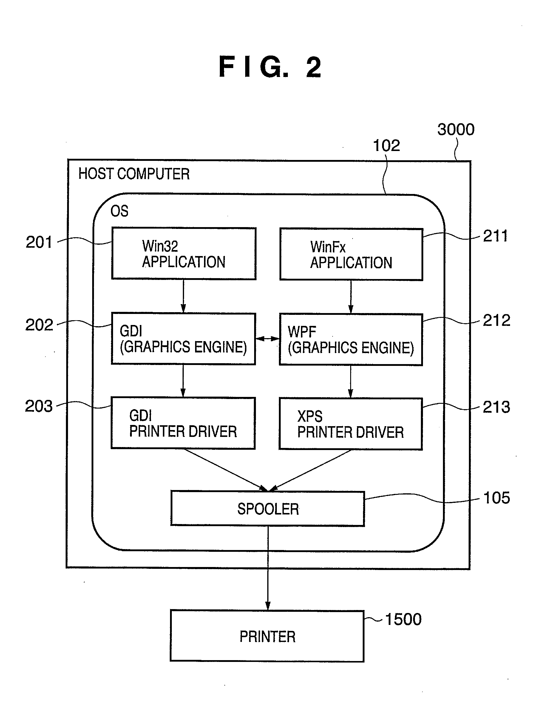
[0118]Print process sequence (1) represents a conventional GDI print path. Rendering data passed from a Win32 application 201 is stored as an EMF spool file 301 in a GDI 202. Then, a GDI printer driver 203 converts the EMF spool file 301 into print data.

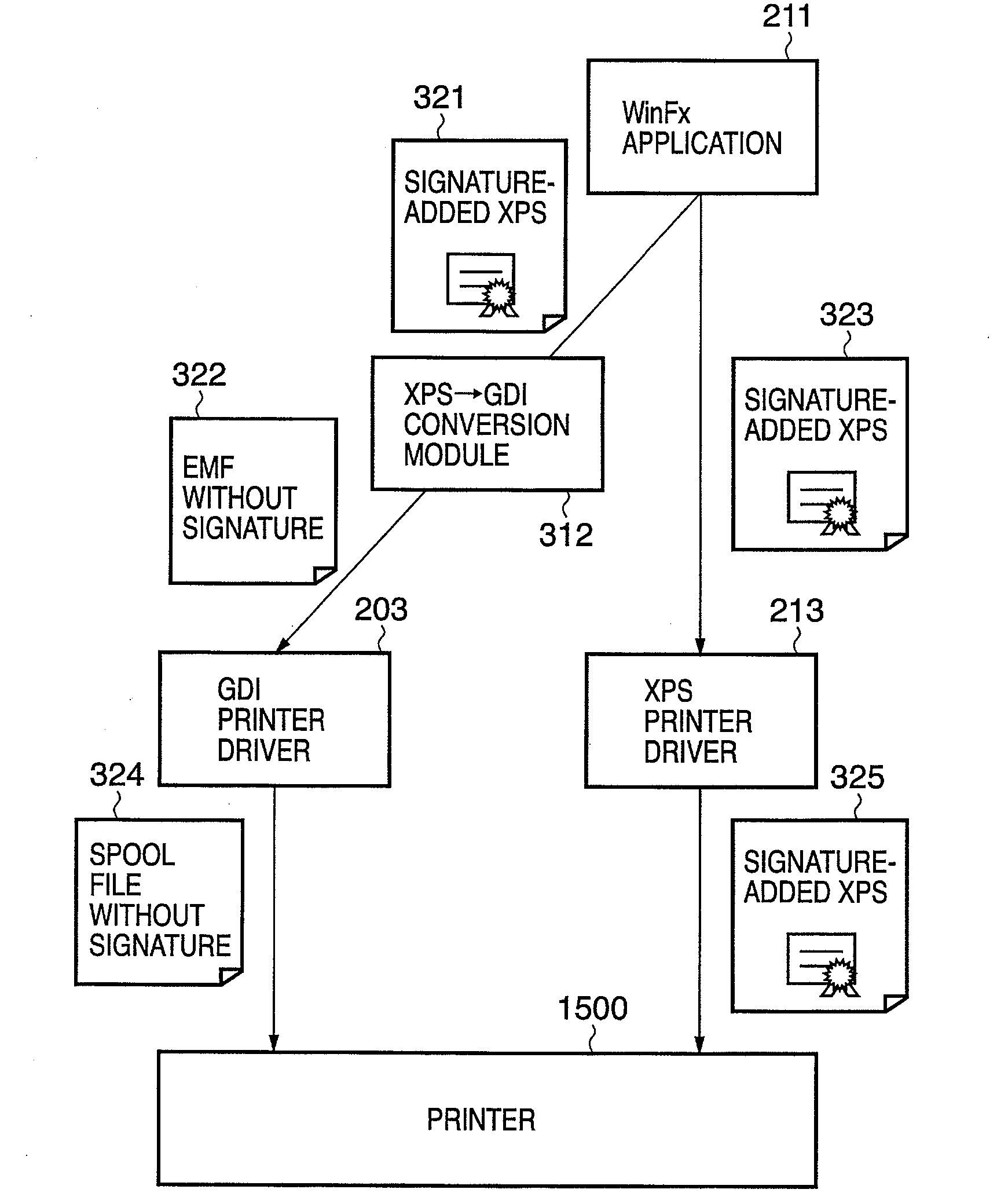
[0119]Print process sequence (4) represents an XPS print path added in Windows® Vista. Rendering data passed from a WinFx application 211 is stored as an XPS spool file 311 in a WPF 212. Then, an XPS printer driver 213 converts the XPS spool file 311 into print data.

[0120]Pri...


PUM


Abstract

It is analyzed on the basis of received print data whether the print data is print data generated via a process path formed from a combination of the first application and first printer driver, or print data generated via a process path formed from a combination of the second application and second printer driver. Settings associated with the process of print data are made for each process path. The process of the received print data is controlled on the basis of the analysis result and setting contents.

Description

BACKGROUND OF THE INVENTION[0001]1. Field of the Invention[0002]The present invention relates to an image forming apparatus which receives print data and prints, a control method therefor, and a program.[0003]2. Description of the Related Art[0004]An application on a host computer prints an image or text from a printing apparatus by generally using an arrangement as shown in FIG. 1.[0005]More specifically, an application 101 on a host computer 3000 passes graphics data to a graphics engine 103. The graphics engine 103 processes the graphics data and passes it to a printer driver 104. The printer driver 104 generates print data (e.g., PDL: Page Description Language) to a printer 1500. The print data is stored in a spooler 105 and then sent to the printer 1500.[0006]In particular, the graphics engine 103 converts the resolution of graphics data created by the application 101, and processes graphics data by a simulation process or the like in accordance with the performance of the prin...

Claims


Application Information

Patent Timeline
IPC IPC(8): G06F3/12
CPCG06F3/1208G06F3/1222G06F3/1238G06F21/608G06F3/126G06F3/1285G06F3/1239
Inventor NAKAMURA, TADAHIRO
Owner CANON KK
Why Eureka
Try Eureka