
Key cutting machine

a cutting machine and key technology, applied in the field of key cutting machines, can solve the problems of inability to accurately reproduce other types of keys, inability to cut other types of keys known in the field, and devices only capable of cutting standard keys

Active Publication Date: 2007-09-20
HY KO PRODS
View PDF25 Cites 13 Cited by
  • Summary
  • Abstract
  • Description
  • Claims
  • Application Information

AI Technical Summary

Problems solved by technology

However, these devices are only capable of cutting standard keys.
As a result, these devices cannot cut other types of keys known in the field.
By having only one type of key cutting machine, facilities cannot accurately reproduce other types of keys.
Another deficiency of key cutting and duplicating machines is that the cutting tool is typically driven through an intermediate belt and pulley assembly by the output shaft of a driving motor.
This increases not only the number of the parts, but also the transmission friction loss.
Yet another deficiency of key cutting and duplicating machines is that a spring biased carriage system is utilized that can cause the clamp members and carriage to prematurely disengage during the final cutting portion of the key tip.
Therefore, the cutting wheel tends to slide off of the end of the key blank and therefore not complete the key pattern.
Presently, there is no known key cutting machine or method that avoids the problems associated with the known devices listed above.

Method used


Image

  • Key cutting machine
  • Key cutting machine
  • Key cutting machine

Examples


Embodiment Construction

[0023] While the present invention is described with reference to embodiments described herein, it should be clear that the present invention is not limited to. such embodiments. Therefore, the description of the embodiments herein is merely illustrative of the present invention and will not limit the scope of the invention as claimed.

[0024] With reference to FIGS. 10 and 11, a brief introduction to key blanks and master keys is as follows. A key blank 100 generally comprises a head 102, a shoulder 104, and a blade 106. Key blanks can also be provided with keyway grooves 108 which are long, narrow, milled-out areas along the sides of the blade 106 that allow the blade 106 to bypass the wards in the keyway. Such keyway grooves 108 may previously be cut into a key blank so as to simplify the key cutting operation. Therefore, when duplicating a master key, a key blank 100 must be identified as either identical to or similar to the master key. The key blank 100 is cut from a master key...


PUM

PropertyMeasurementUnit
transmission friction lossaaaaaaaaaa
structureaaaaaaaaaa
depthaaaaaaaaaa

Abstract

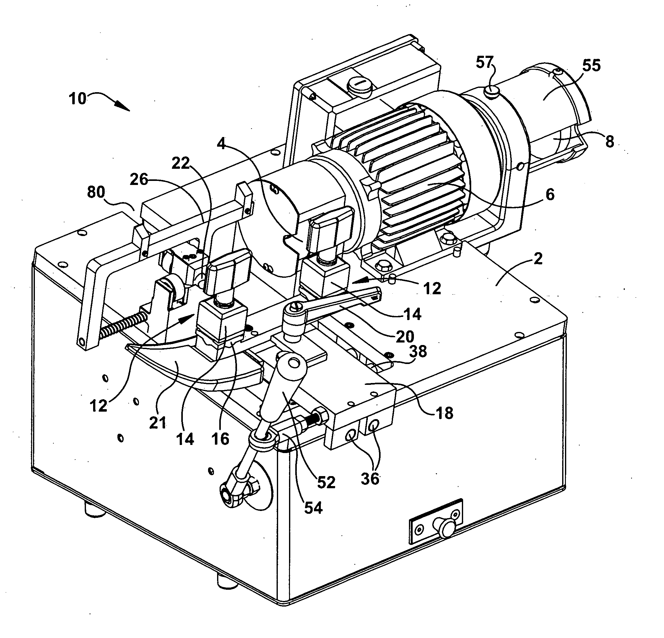
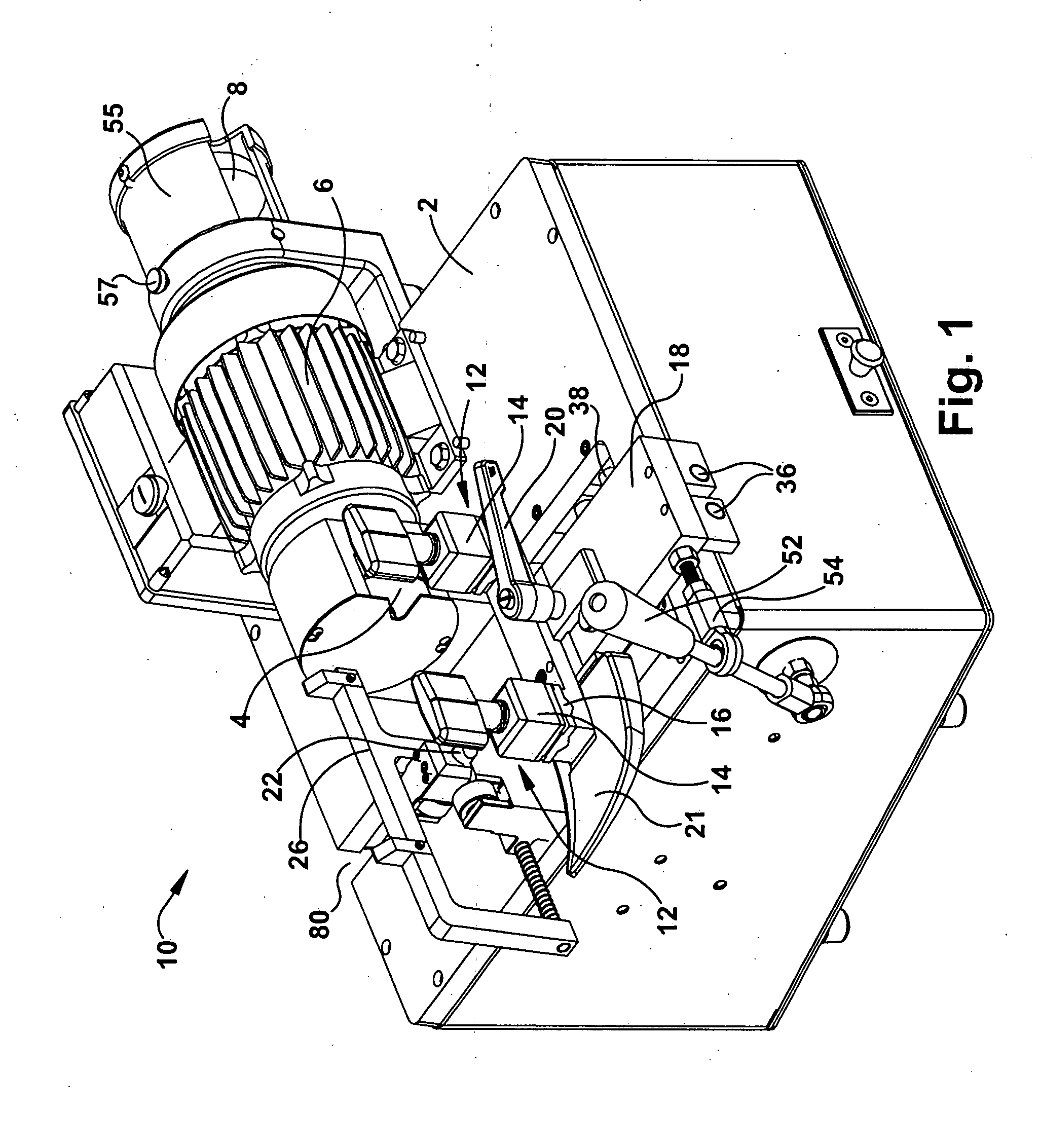
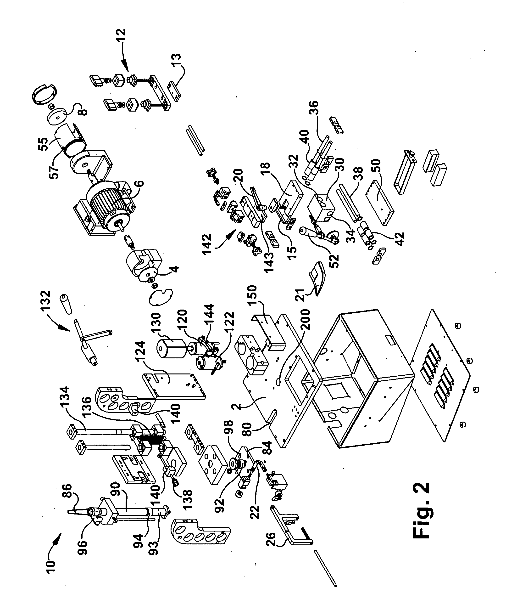
A key cutting machine is provided for cutting a key blank from a master key. The key cutting machine comprises a first cutting member that rotates about a substantially horizontal axis for cutting a key pattern on a key blank and a second cutting member that rotates about a substantially vertical axis for cutting a key pattern on a key blank. Additional improvements or features of a key cutting machine are also described.

Description

CROSS-REFERENCE TO RELATED APPLICATION [0001] This application claims the benefit of priority of U.S. Provisional Patent Application Ser. No. 60 / 775,476, entitled: “KEY CUTTING MACHINE,” filed on Feb. 22, 2006, which is hereby incorporated in its entirety by reference.FIELD OF THE INVENTION [0002] The present invention generally relates to a key cutting machine, and particularly, to a key cutting machine that is capable of cutting a standard key and a sidewinder key. BACKGROUND OF THE INVENTION [0003] There are several types of key cutting machines used in the industry. Generally, these key cutting machines cut only one type of key known in the field. For example, conventional key cutters use a cutting member, such as, a circular rotating saw-like blade to cut a key pattern in the blade of a standard key blank. These cutting machines generally include a pair of vise grips or clamps mounted on a carriage. A master key having a key pattern previously cut therein is placed in one clamp...

Claims


Application Information

Patent Timeline
Patent Type & Authority Applications(United States)
IPC IPC(8): B23C3/35
CPCY10T409/300952B23C3/35B23C2235/08B23C2235/48
Inventor RYAI, RICHARD W. SR.
Owner HY KO PRODS
Learn More