Connector structure and connector type terminal block structure

a technology of connector type and connector type, applied in the direction of one-pole connection, coupling device details, coupling device connection, etc., can solve the problem of not fully ensuring the electrical connection by the contact poin

Active Publication Date: 2007-09-20
TOYOTA JIDOSHA KK +1
View PDF2 Cites 38 Cited by
  • Summary
  • Abstract
  • Description
  • Claims
  • Application Information

AI Technical Summary

Benefits of technology

[0008]The present invention has been made to solve the problem described above, and an object thereof is to provide a connector structure and a connector type terminal block structure that can further ensure an electric connection between a first connector component and a second connector component.
[0010]In the connector structure as configured above, the rotary members are twisted relative to the frame member and thereby biased relative to the second connector component. Therefore, by changing the width of a connecting portion between the frame member and the rotary members, the biasing force to the rotary member toward the second connector component can be adjusted. As a result, the contacting force between the second connector component and the rotary members can be changed as appropriate to realize the ensured connection. Additionally, since the frame member and the rotary members are formed from working of a common conductive plate, the manufacturing costs can be reduced relative to the case where the frame member and the rotary members are formed with separate members.
[0012]In this case, the tilt surface contacts the second connector component, whereby the second connector component can smoothly be inserted.
[0013]Preferably, the opening is defined by a second inner surface opposing to the first inner surface. The first inner surface is provided with a plurality of first protrusions in a forward-backward direction of insertion of the second connector component relative to the rotary members, whereby abutment on the second connector component is enabled, and the second inner surface is provided with a second protrusion between the plurality of first protrusions that can abut on the second connector component. In this case, the second connector component is inserted into the space between the first and second protrusions. Thus, the second connector component is inserted in a narrow space. As a result, it is less likely that the second connector component is inserted from an unprescribed direction, and the second connector component does not put movable load on the rotary members. As a result, further ensured connection between the second connector member and the rotary members is realized.
[0015]The connector type terminal structure configured as above achieves a structure in which the first connector component contacts the second connector component at a plurality of contacting points, and the stator terminal and the first connector component are fixed to the base member using the fixing member. As a result, even when the stator terminal vibrates, the vibration is stopped by the fixing member and the base member to prevent propagation of the vibration to the first and second connector components. As a result, the contact between the first and second connector components can further be ensured. Further, even when the rotating electric machine vibrates, the precision in the fastening position of the stator bus bar can be ensured against the vibration of the rotating electric machine.
[0017]According to the present invention, a connector structure that can further surely maintain an electric connection and a connector type terminal block structure using the same can be provided.

Problems solved by technology

Although in the conventional terminal structure a contact point corresponding to “a first contact point” for connecting a feeding cable and an inner conductor has been provided, there has been a problem that an electric connection by the contact point is not fully ensured.

Method used


Image

  • Connector structure and connector type terminal block structure
  • Connector structure and connector type terminal block structure
  • Connector structure and connector type terminal block structure

Examples


first embodiment

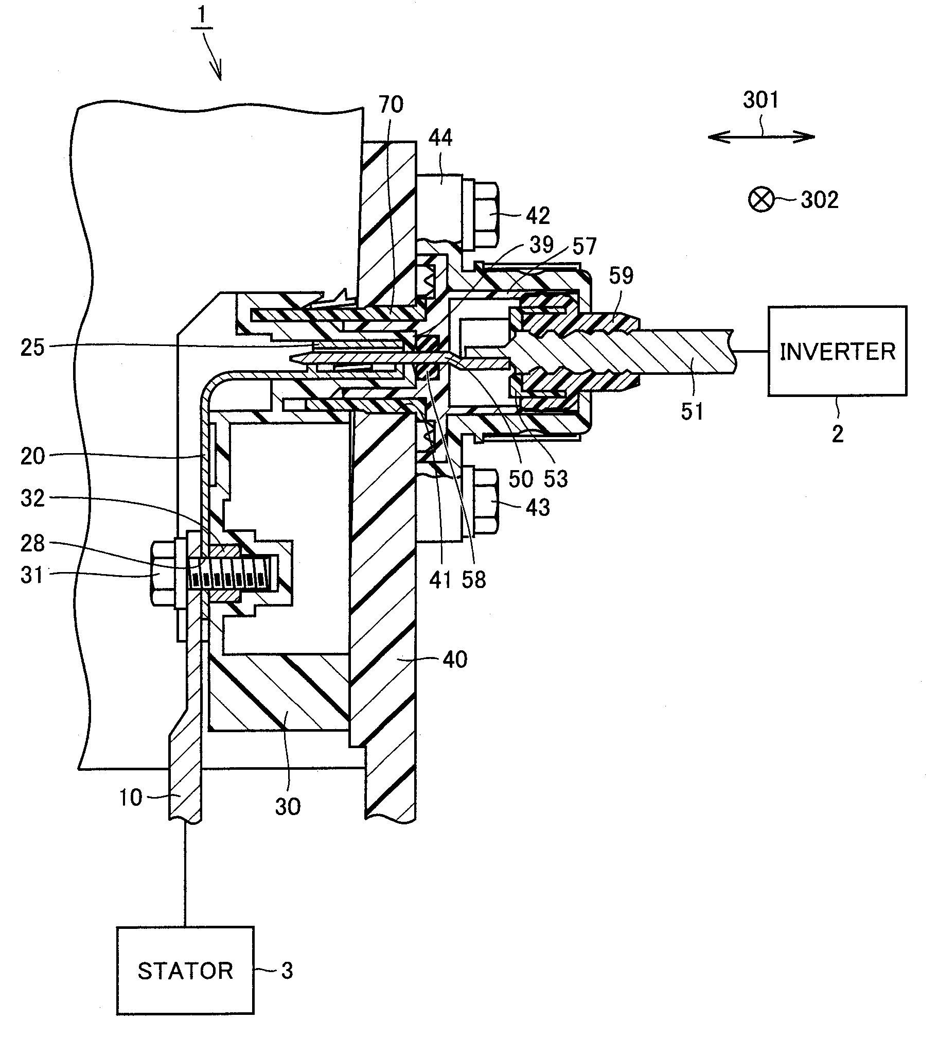
[0028]FIG. 1 is a cross-sectional view of a connector type terminal block structure according to a first embodiment of the present invention. Referring to FIG. 1, in a connector type terminal block I according to the first embodiment of the present invention, a base member 30 is fixed to a housing 40. A nut 32 is fixed to base member 30. A bolt 31 is fastened to nut 32. Bolt 31 fixes a stator terminal 10 connected to a stator 3 and a bus bar 20.

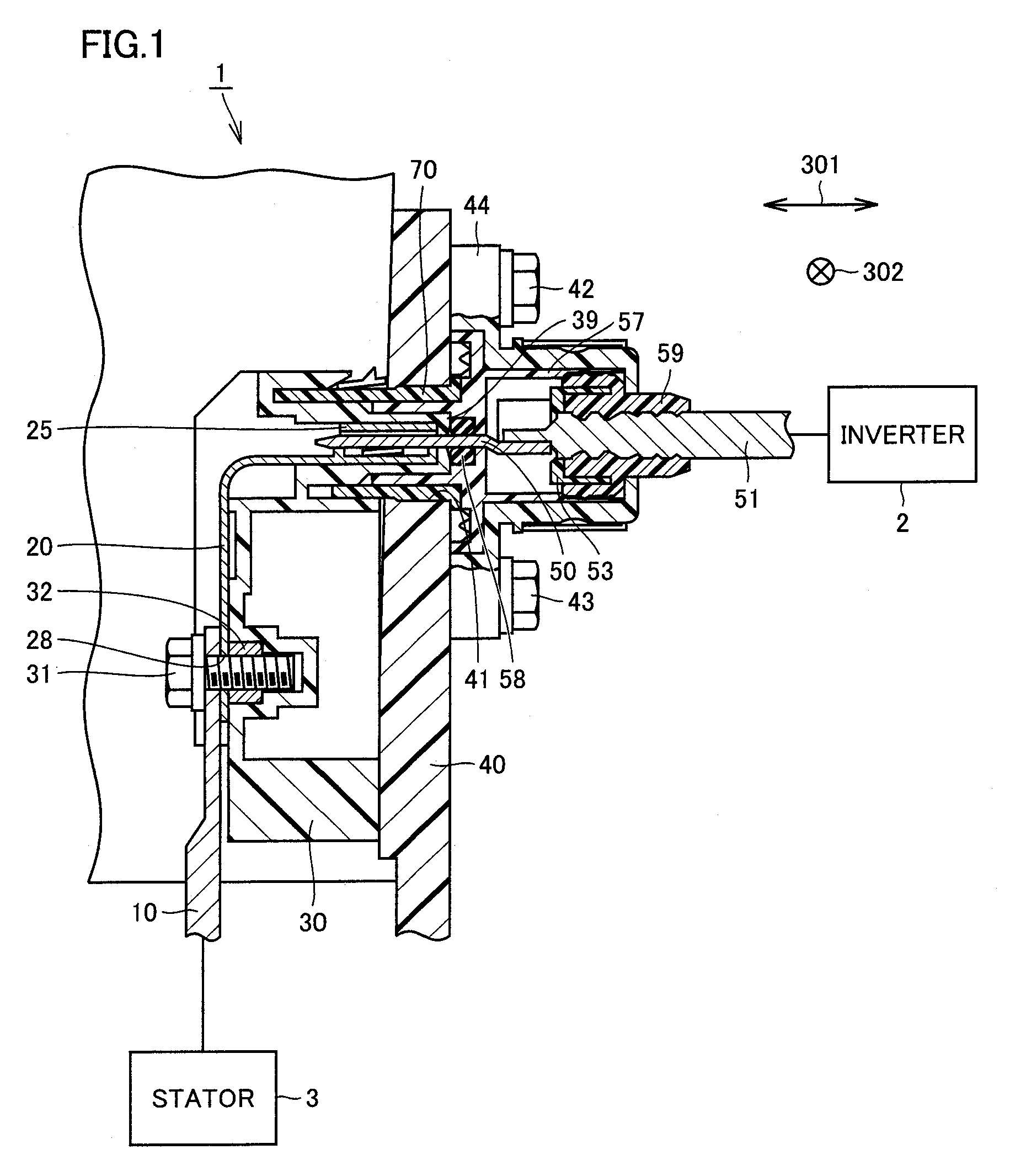
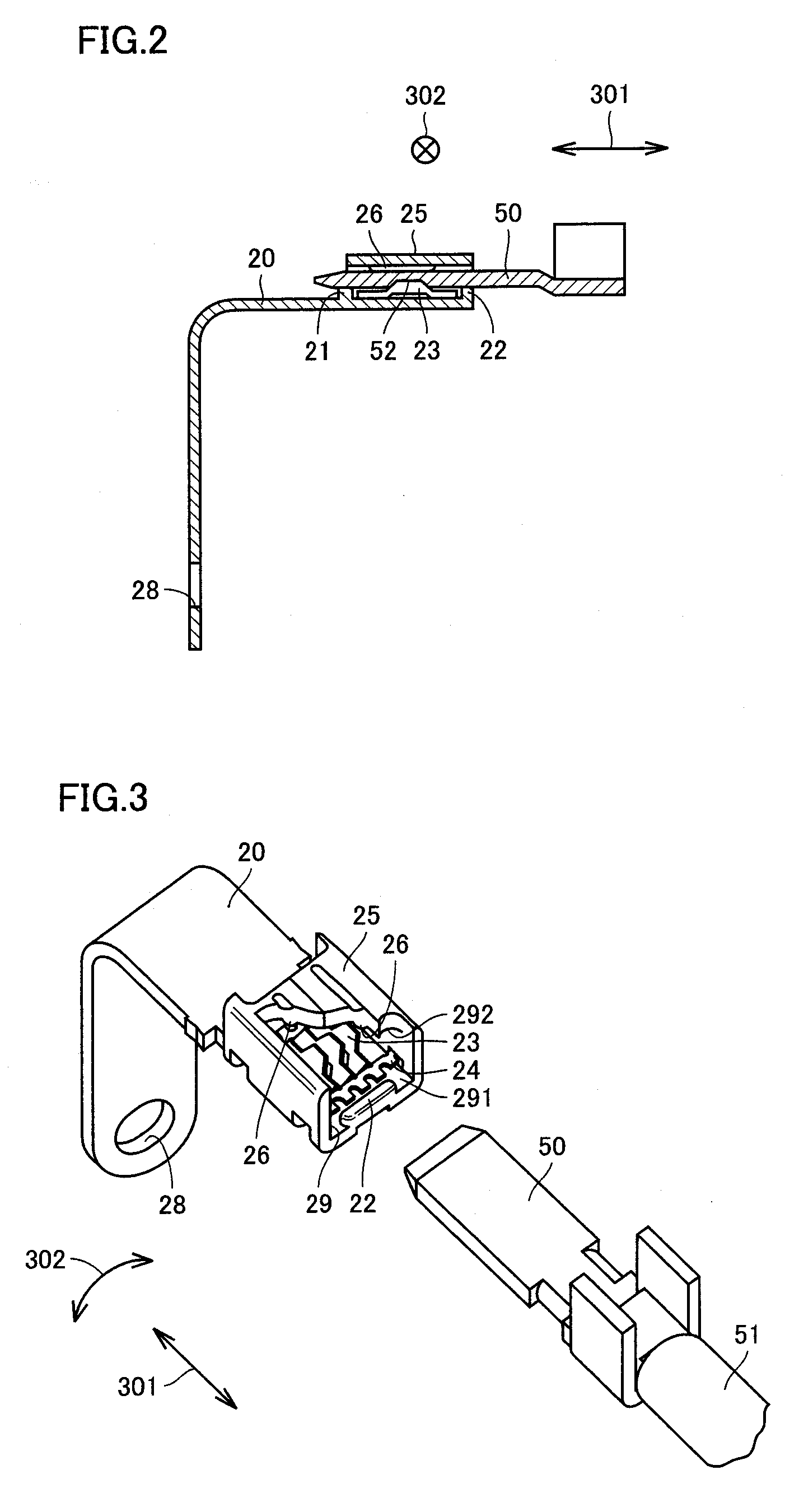
[0029]Inverter 2 is connected to a conductor 51, which is connected to a plate-like terminal 50. Plate-like terminal 50 mates with a tip portion of bus bar 20. Conductor 51 is covered by a cap member 59, and sealed by a seal member 53. Cap member 59 is held by a cover member 44, which is fixed to housing 40 by bolts 42 and 43. Between base member 30 and seal member 57, another seal member 58 formed of an elastic body is provided.

[0030]Housing 40 stores a stator 3 constituting a rotating electric machine. Stator 3 is supplied with electric pow...


PUM


Abstract

A connector structure that can ensure connection is provided. In the connector structure, a bus bar and a plate-like terminal mate with each other to establish an electric connection. A lower-side inner surface as a first inner surface defining the opening is provided with a plurality of conductive rotary members that rotate in a direction substantially perpendicular to a direction in which the plate-like terminal is inserted. It is also provided with a frame member that holds the rotary members and that is connected to the bus bar. The rotary members are twisted relative to the frame member and thereby biased relative to the plate-like terminal. By the plate-like terminal being inserted into and pulled out from the bus bar, the rotary members receive force from the plate-like terminal and rotate within a plane substantially perpendicular to a direction in which the plate-like terminal is inserted and pulled out.

Description

[0001]This nonprovisional application is based on Japanese Patent Application No. 2006-072409 filed with the Japan Patent Office on Mar. 16, 2006, the entire contents of which are hereby incorporated by reference.BACKGROUND OF THE INVENTION[0002]1. Field of the Invention[0003]The present invention relates to a connector structure and to a connector type terminal block structure. More specifically, the present invention relates to a connector structure connected to a rotating electric machine incorporated in a vehicle and to a connector type terminal block structure using the same.[0004]2. Description of the Background Art[0005]Conventionally, a connector type terminal block structure has been disclosed in Japanese Patent Laying-Open No. 2005-229755, for example.[0006]The publication discloses a technique in which a flexible member is provided between a winding and a terminal block in order to absorb the tolerance of components in assembling the varnished motor winding to the termina...

Claims


Application Information

Patent Timeline
Patent Type & Authority Applications(United States)
IPC IPC(8): H01R13/64
CPCH01R11/01H01R13/113H01R13/187H01R13/5205H01R13/521H01R2201/26H01R13/748H01R24/28H01R24/76H01R2101/00H01R13/743
Inventor TAKIZAWA, KEIJIFUJIMOTO, KEI
Owner TOYOTA JIDOSHA KK
Why Eureka
Try Eureka