Flow control methodology for digital retiming devices

a technology of flow control and digital retiming, applied in the direction of digital transmission, data switching network, instruments, etc., can solve the problems of increased size, speed and complexity, difficult diagnosis and resolution, and demand for communication bandwidth

Active Publication Date: 2007-09-20
VIAVI SOLUTIONS INC
View PDF5 Cites 16 Cited by
  • Summary
  • Abstract
  • Description
  • Claims
  • Application Information

AI Technical Summary

Benefits of technology

[0007]Embodiments disclosed herein relate to a network diagnostic device or component such as a network analyzer or a jammer that is placed in-line between two nodes in a network to perform a flow control operation transparently without the requirement of a ...

Problems solved by technology

Computer and data communications networks continue to proliferate due to declining costs, increasing performance of computer and networking equipment, and increasing demand for communication bandwidth.
As communication networks have increased in size, speed and complexity however, they have become increasingly likely to develop a variety of problems that, in practice, have proven difficult to diagnose and resolve.
The problems generally experienced in network communications can take a variety of forms and may occur as a r...

Method used


Image

  • Flow control methodology for digital retiming devices
  • Flow control methodology for digital retiming devices
  • Flow control methodology for digital retiming devices

Examples


Embodiment Construction

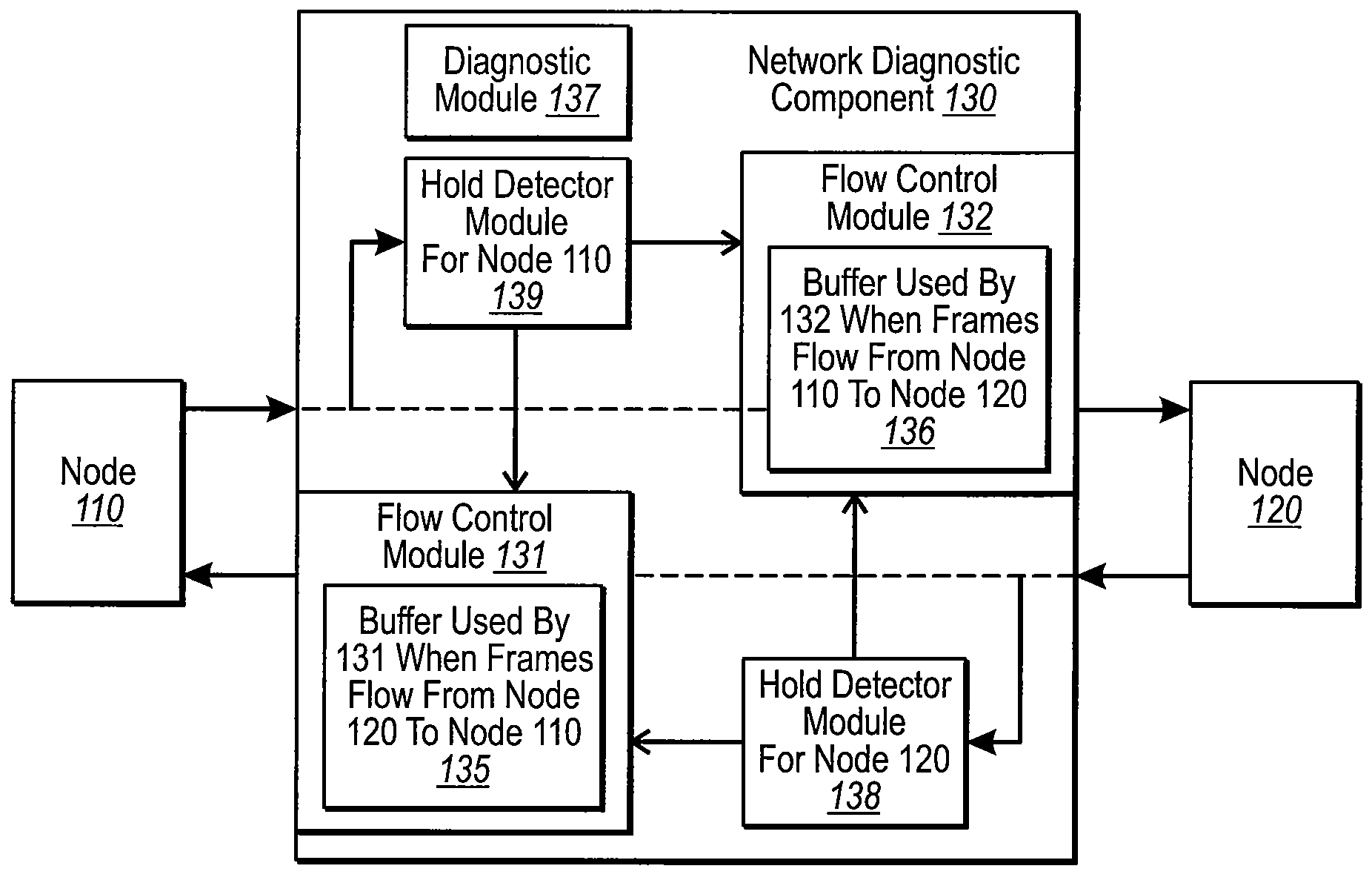
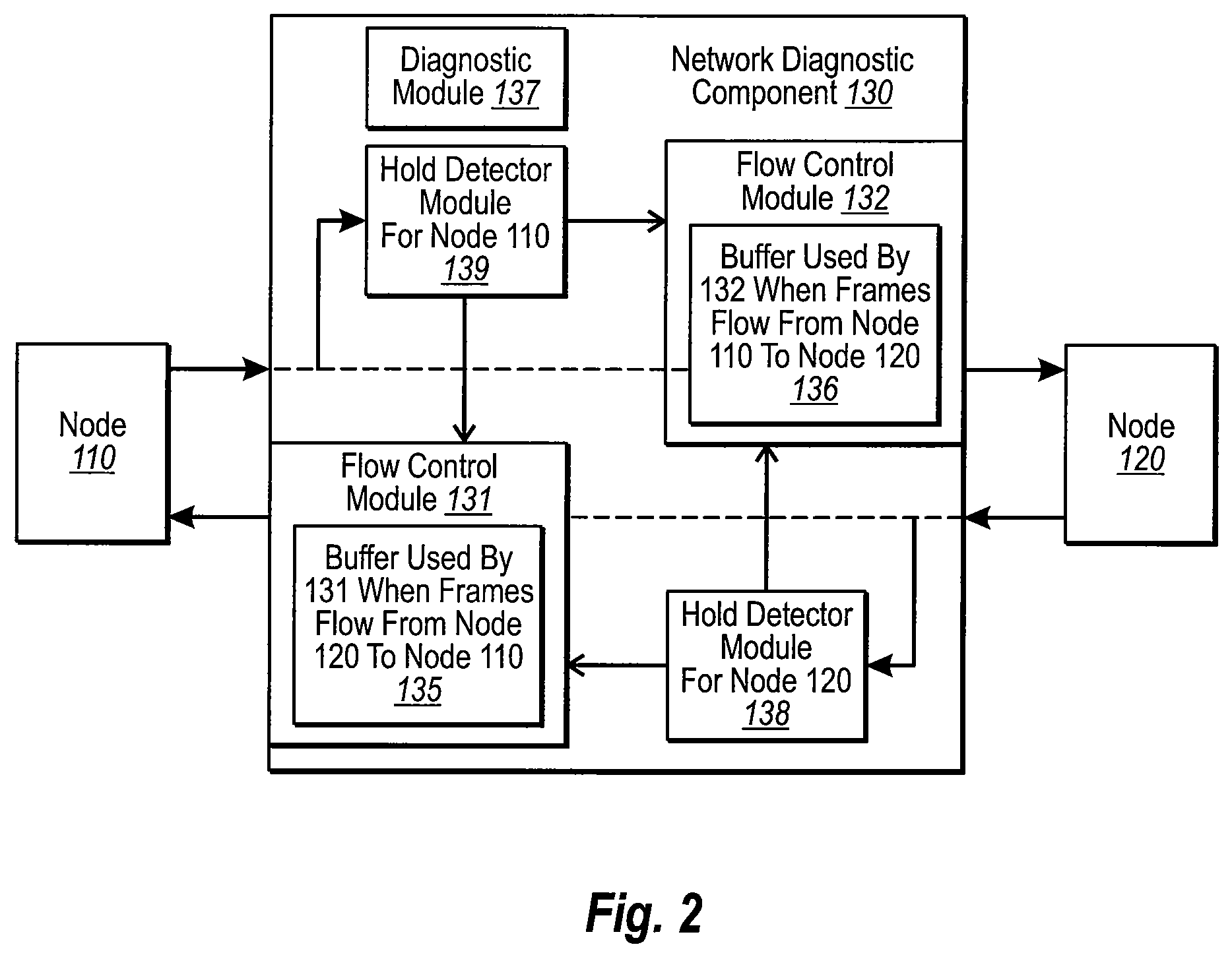
[0018]Embodiments disclosed herein relate to a network diagnostic device or component such as a network analyzer or a jammer that is placed in-line between two nodes in a network to perform a flow control operation transparently without the requirement of a separate link layer implementation. The network diagnostic device may include a diagnostic module configured to perform network analyzer operations, a first memory or buffer, a second memory or buffer, a first flow control module, and a second flow control module.

[0019]In some embodiments, when performing the flow control operation, various modules and / or components may cause the network diagnostic device to enter a first pass-through mode and to then enter into a first flow control handshaking mode from the first pass-through mode. The various modules and / or components may also cause the network diagnostic device to enter a second pass-through mode from the first flow control handshaking mode and to then enter into a second flow...


PUM


Abstract

A network diagnostic device or component such as a network analyzer or a jammer that is placed in-line between two nodes in a network to perform a flow control operation transparently without the requirement of a separate link layer implementation. The network diagnostic device may include a diagnostic module configured to perform network analyzer operations, a memory a first flow control module a second flow control module. In some embodiments, when performing the flow control operation, various modules and/or components may cause the network diagnostic device to enter a first pass-through mode and to then enter into a first flow control handshaking mode from the first pass-through mode. The various modules and/or components may also cause the network diagnostic device to enter a second pass-through mode from the first flow control handshaking mode and to then enter into a second flow control handshaking mode from the first pass-through mode.

Description

CROSS-REFERENCE TO RELATED APPLICATIONS[0001]This application claims the benefit of U.S. Provisional Application No. 60 / 773,472, filed Feb. 14, 2006, and U.S. Provisional Application No. 60 / 778,792, filed Mar. 3, 2006, both of which are incorporated herein by reference in their entirety.BACKGROUND[0002]Computer and data communications networks continue to proliferate due to declining costs, increasing performance of computer and networking equipment, and increasing demand for communication bandwidth. Communications networks—including wide area networks (“WANs”), local area networks (“LANs”), metropolitan area networks (“MANs”), and storage area networks (“SANS”)—allow increased productivity and use of distributed computers or stations through the sharing of resources, the transfer of voice and data, and the processing of voice, data and related information at the most efficient locations. Moreover, as organizations have recognized the economic benefits of using communications networ...

Claims


Application Information

Patent Timeline
IPC IPC(8): G06F11/00
CPCH04K3/46H04K2203/18H04L43/50H04L43/0847H04L43/18H04L12/2697
Inventor VEDANABHATLA, KIRANMAIHIBBERT, GEOFFREY T.
Owner VIAVI SOLUTIONS INC
Why Eureka
Try Eureka