
Show oob and speed negotiation data graphically in a network diagnostic component

a network diagnostic and data graphic technology, applied in data switching networks, frequency-division multiplexes, instruments, etc., can solve problems such as difficulty in diagnosing and solving, increased size, speed and complexity, and increased communication bandwidth

Active Publication Date: 2008-08-07
VIAVI SOLUTIONS INC
View PDF51 Cites 15 Cited by
  • Summary
  • Abstract
  • Description
  • Claims
  • Application Information

AI Technical Summary

Problems solved by technology

Computer and data communications networks continue to proliferate due to declining costs, increasing performance of computer and networking equipment, and increasing demand for communication bandwidth.
As communication networks have increased in size, speed and complexity however, they have become increasingly likely to develop a variety of problems that, in practice, have proven difficult to diagnose and resolve.
The problems generally experienced in network communications can take a variety of forms and may occur as a result of a variety of different circumstances.
Examples of circumstances, conditions and events that may give rise to network communication problems include the transmission of unnecessarily small frames of information, inefficient or incorrect routing of information, improper network configuration and superfluous network traffic, to name just a few.
Such problems are aggravated by the fact that networks are continually changing and evolving due to growth, reconfiguration and introduction of new network topologies and protocols.

Method used


Image

  • Show oob and speed negotiation data graphically in a network diagnostic component
  • Show oob and speed negotiation data graphically in a network diagnostic component
  • Show oob and speed negotiation data graphically in a network diagnostic component

Examples


Embodiment Construction

[0019]The embodiments disclosed herein may be practiced in networking systems, including the testing of high speed data transmission systems and components. Embodiments described herein may also be used in other contexts unrelated to testing systems and components and / or unrelated to high speed data transmission. An example networking system will first be described. Then, the operation in accordance with specific embodiments disclosed herein will be described. Note that as used herein, the terms “first”, “second” and so forth are not intended to imply sequential ordering, but rather are intended to distinguish one element from another unless explicitly stated.

Example Networking System

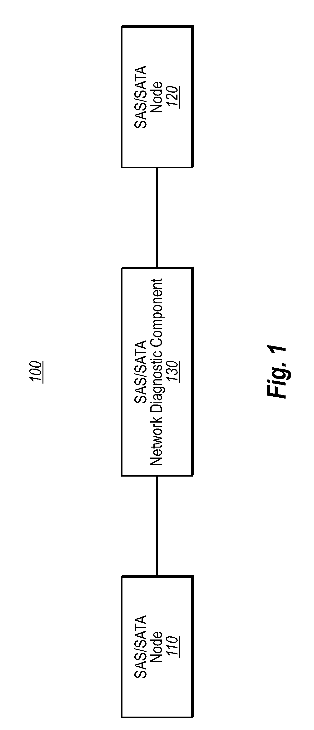
[0020]FIG. 1 is a block diagram of a networking system 100. The networking system 100 may include one or more nodes 110, 120, which communicate with each other via a network. As used herein, a “node” includes, but is not limited to, a server or host; a client or storage device; a switch; a hub; a router...


PUM


Abstract

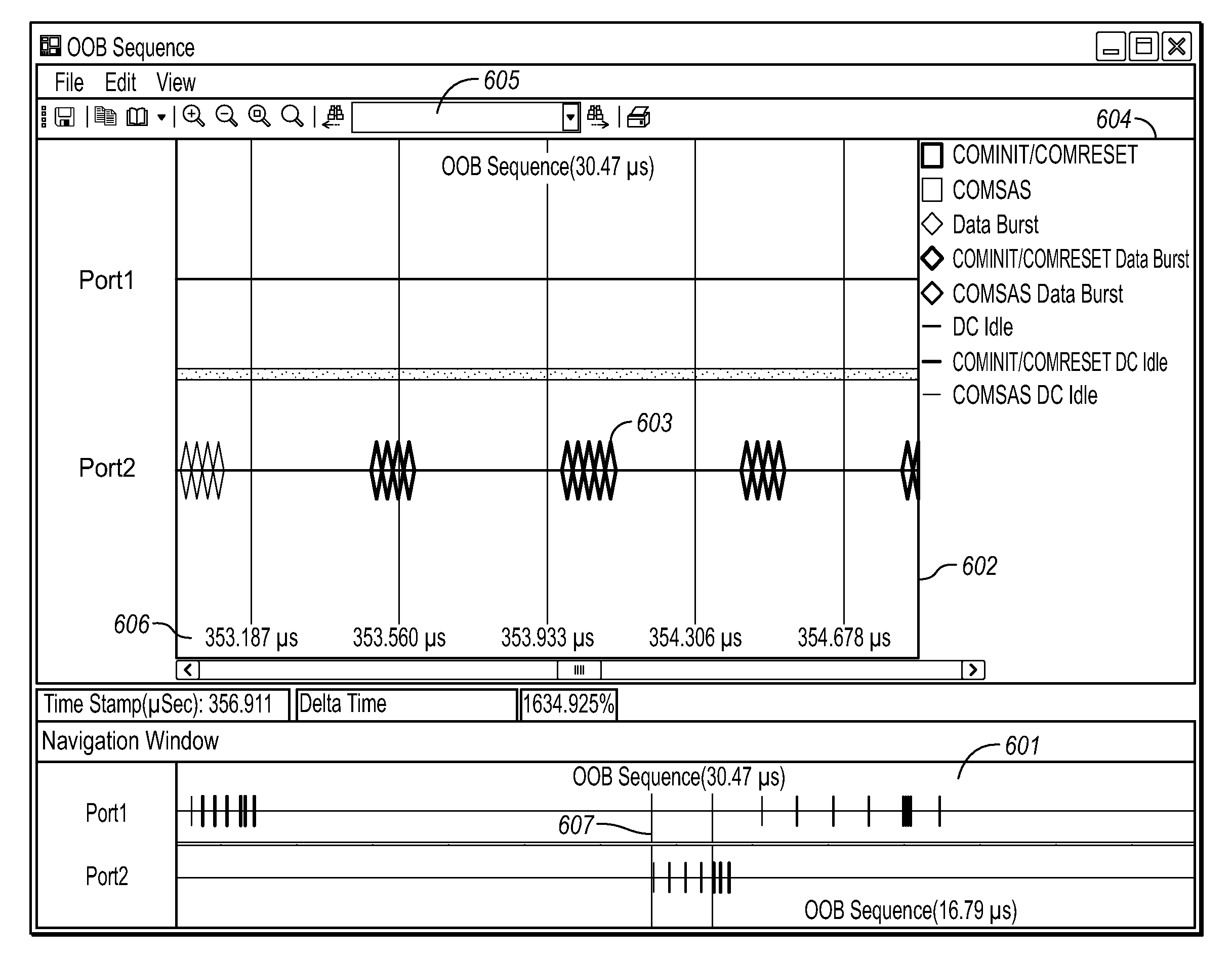
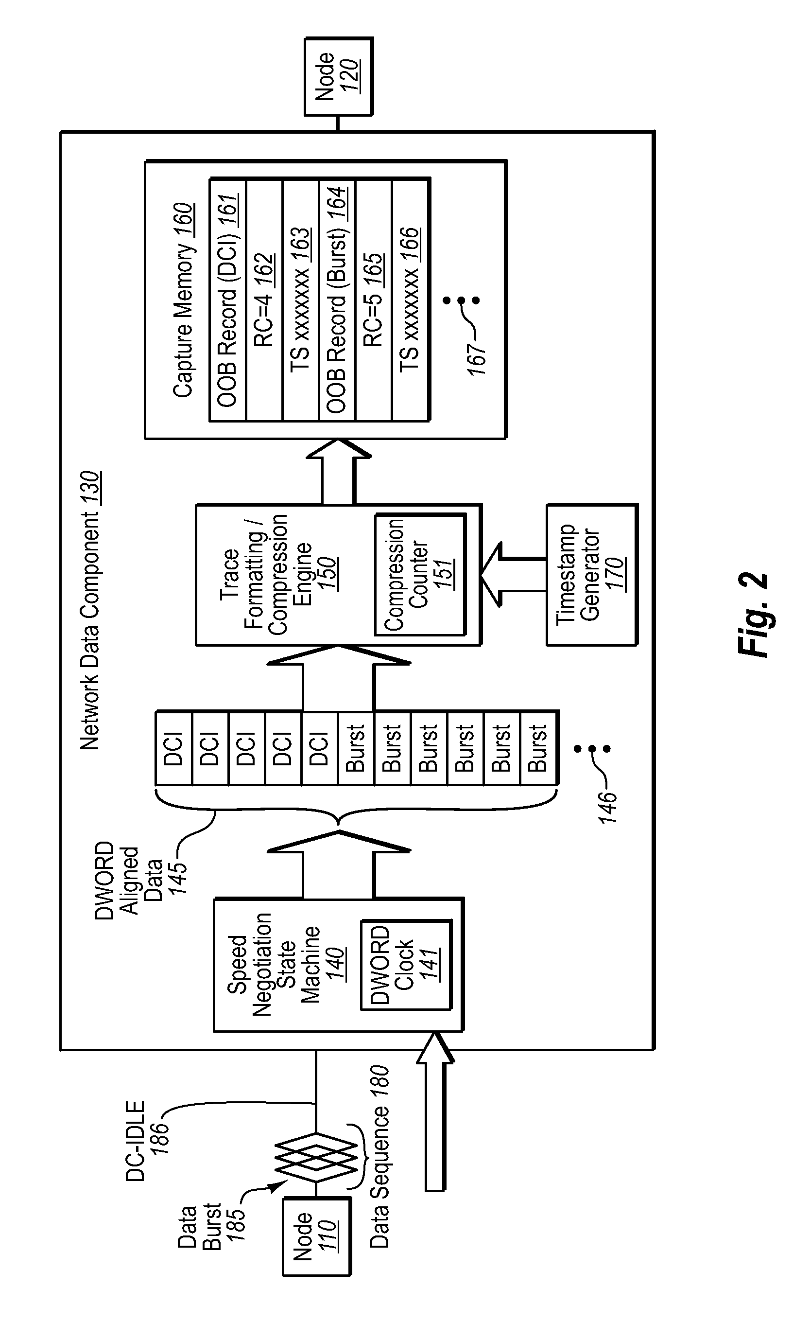
A network diagnostic component that is placed in-line between two nodes in a network. The network diagnostic component receives a low speed signal pattern from the first node for communication with the second node; records the low speed signal pattern in a memory writes one or more markers specifying information about the low speed signal pattern in the memory interprets the one or more markers to ascertain the type and duration of the low speed signal pattern; and displays a graphical representation of the low speed signal pattern based on the interpretation of the one or more markers.

Description

CROSS-REFERENCE TO RELATED APPLICATIONS[0001]This patent application is a Continuation-in-Part of U.S. patent application Ser. No. 11 / 675,041, filed Feb. 14, 2007, which claims the benefit of U.S. Provisional Application No. 60 / 779,040, filed Mar. 3, 2006. This patent application is also a Continuation-in-Part of U.S. patent application Ser. No. 11 / 675,045, filed Feb. 14, 2007, which claims the benefit of U.S. Provisional Application No. 60 / 773,515, filed Feb. 14, 2006. This patent application also claims the benefit of U.S. Provisional Application No. 60 / 909,684, filed Apr. 2, 2007. All of the aforementioned patent applications are incorporated herein by reference in their entirety.BACKGROUND[0002]Computer and data communications networks continue to proliferate due to declining costs, increasing performance of computer and networking equipment, and increasing demand for communication bandwidth. Communications networks—including wide area networks (“WANs”), local area networks (“LA...

Claims


Application Information

Patent Timeline
Patent Type & Authority Applications(United States)
IPC IPC(8): G06F3/048
CPCH04J3/14H04L43/18H04L43/045
Inventor KOTTURU, VENKATA RAMA MOHANA RAOVEDANABHATLA, KIRANMAI
Owner VIAVI SOLUTIONS INC
Learn More