Cabeless interconnect system for pick and place machine

a cableless and pick-and-place machine technology, applied in metal-working equipment, metal-working equipment, manufacturing tools, etc., can solve the problems of large number of cables and wires required, difficult assembly and space consumption

Inactive Publication Date: 2007-09-27
UI HLDG
View PDF18 Cites 12 Cited by
  • Summary
  • Abstract
  • Description
  • Claims
  • Application Information

AI Technical Summary

Benefits of technology

[0010] According to one aspect of the present invention, a pick and place head for a pick and place machine comprises a stationary frame; a first circuit board mounted on the stationary frame, the first circuit board including a first plurality of circuits and a first plurality of electric contacts connected to the first plurality of circuits; a rotating frame rotatably mounted to the stationary frame; a plurality of spindle assemblies mounted on the rotating frame; a second circuit board mounted on the rotating frame, the second circuit board including a second plurality of circuits relating to an operation of the plurality of spindle assemblies, and a second plurality of electric contacts connected to the second plurality of circuits; a slip ring assembly mounted between the first circuit board and the second circuit board; the slip ring assembly including a first portion having a third plurality of electric contacts and a second portion having a fourth plurality of electric contacts; the first portion of the slip ring assembly being rotatable relative to the second portion of the slip ring assembly, and the slip ring assembly further including a set of electrical connectors that enable the third plurality of electric contacts to maintain electrical connection with the fourth plurality of electric contacts while the first portion rotates relative to the second portion; the first portion being fixed relative to the first circuit board so that the third plurality of electric contacts are in electrical connection with the first plurality of electric contacts and the second portion being fixed relative to the second circuit board so that the fourth plurality of electric contacts are in electrical connection with the second plurality of electric contacts; the second circuit board further including a fifth plurality of electric contacts, the fifth plurality of electric contacts engaged with respective contacts of the plurality of spindl_assemblies; a bus connector connected to the first plurality of circuits so as to provide power and control signals to the pick and place head; and a motor to rotate the rotating frame.
[0011] According to another aspect of the present invention, a pick and place head for a pick and place machine comprises a stationary frame; a first circuit board mounted on the stationary frame, the first circuit board including a first plurality of electric circuits; a rotating frame rotatably mounted to the stationary frame; a plurality of spindle assemblies mounted on the rotating frame, each of the plurality of spindle assemblies including a set of electric contacts; a second circuit board mounted on the rotating frame, the second circuit board including a second plurality of electric circuits; a slip ring assembly mounted between the first circuit board and the second circuit board; the slip ring assembly including a first portion and a second portion; the first portion of the slip ring assembly being rotatable relative to the second portion of the slip ring assembly, and the slip ring assembly further including a set of electrical connectors that enable the first plurality of electric circuits to maintain electrical connection with the second plurality of electric circuits while the first portion rotates relative to the second portion; the second circuit board further including a plurality of electric contacts, the plurality of electric contacts on the second circuit board engaged with respective ones of the contacts of the plurality of spindle assemblies; a connector connected to the first plurality of circuits so as to provide power and control signals to the pick and place head; and a motor to rotate the rotating frame.
[0012] According to yet another aspect of the present invention, a pick and place head for a pick and place machine comprises a stationary frame; a first circuit board mounted on the stationary frame, the first circuit board including a first plurality of electric circuits; a rotating frame rotatably mounted to the stationary frame; a plurality of spindle assemblies mounted one the rotating frame, each of the plurality of spindle assemblies including a set of electric contacts; a second circuit board mounted on the rotating frame, the second circuit board including a second plurality of electric circuits; cableless means arranged between the first circuit board and the second circuit board for providing an electric connection between the first plurality of circuits and the second plurality of circuits while the rotating frame rotates relative to the stationary frame; the second circuit board further including a plurality of electric contacts, the plurality of electric contacts on the second circuit board engaged with respective ones of the contacts of the plurality of spindle assemblies; a connector connected to the first plurality of circuits so as to provide power and control signals to the pick and place head; and a motor to rotate the rotating frame.

Problems solved by technology

However, such systems were cumbersome in that the large number of cables and wires required were difficult to assemble and space consuming.

Method used


Image

  • Cabeless interconnect system for pick and place machine
  • Cabeless interconnect system for pick and place machine
  • Cabeless interconnect system for pick and place machine

Examples


Embodiment Construction

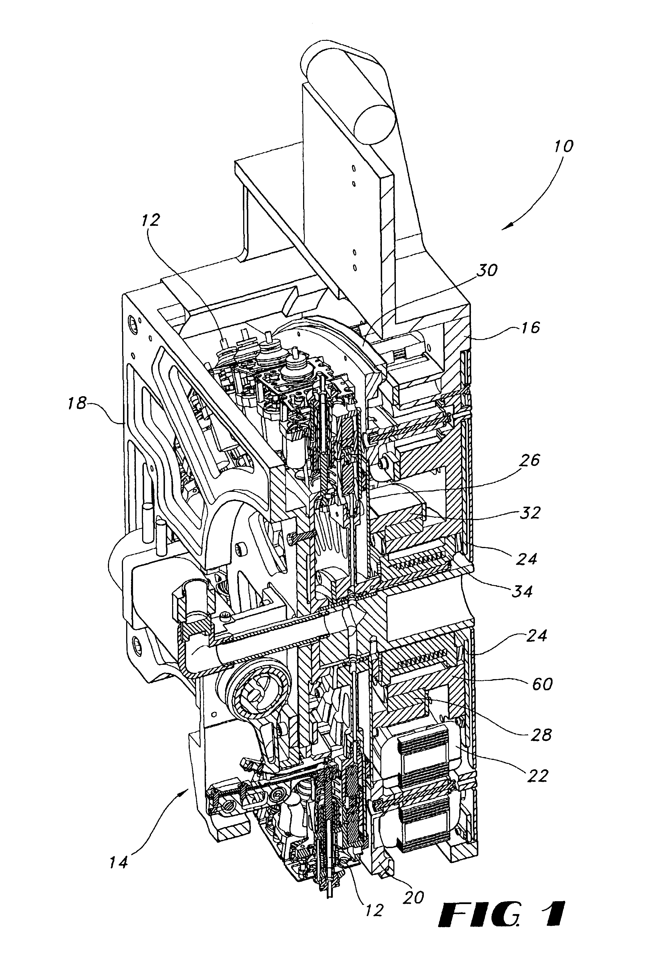
[0016]FIG. 1 is a perspective view of a pick and place head 10 according to a preferred embodiment of the present invention.

[0017] The pick and place head 10 includes a front frame 18 and a rear frame 16. Bearings 28 mounted on the rear frame 16 support a rotating spindle support or frame 20, on which are mounted a plurality of individual spindle assemblies 12. A collar 32 projects from the rotating spindle frame 20 and engages the bearing 28 in order to provide rotatable support for the rotating spindle frame 20.

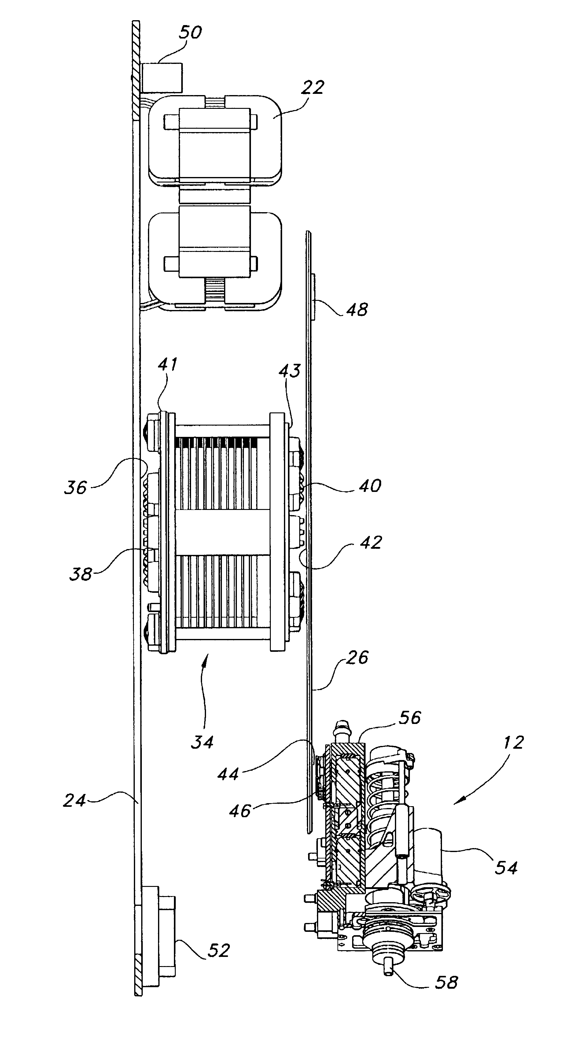
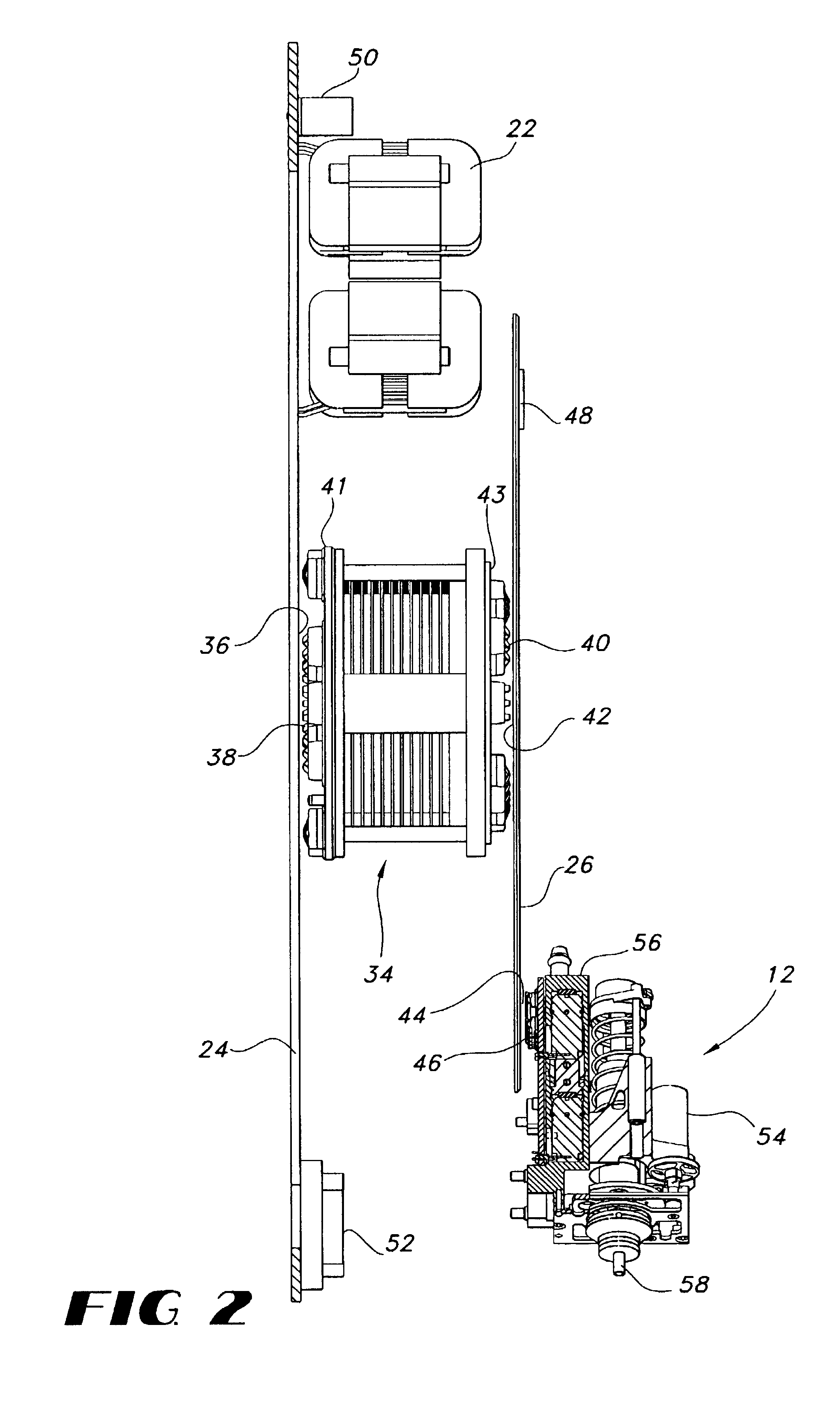
[0018] A motor 22, only a portion of which can be seen in FIG. 1, is mounted circumferentially around the rotating spindle frame 20 for driving the rotating spindle frame 20.

[0019] An encoder 30 is mounted on the rotating spindle frame 20 to provide a signal indicative of the position of the rotating spindle frame 20.

[0020] A spindle driving assembly 14 is mounted to the front frame 18 for actuating whichever spindle assembly is located in the actuating position of the ...


PUM

PropertyMeasurementUnit
vacuum pressureaaaaaaaaaa
poweraaaaaaaaaa

Abstract

A pick and place head for a pick and place machine includes a stationary frame; a first circuit board mounted on the stationary frame, the first circuit board including a first plurality of electric circuits; a rotating frame rotatably mounted to the stationary frame; a plurality of spindle assemblies mounted one the rotating frame, each of the plurality of spindle assemblies including a set of electric contacts; a second circuit board mounted on the rotating frame, the second circuit board including a second plurality of electric circuits; a slip ring assembly mounted between the first circuit board and the second circuit board; the slip ring assembly including a first portion and a second portion; the first portion of the slip ring assembly being rotatable relative to the second portion of the slip ring assembly, and the slip ring assembly further including a set of electrical connectors that enable the first plurality of electric circuits to maintain electrical connection with the second plurality of electric circuits while the first portion rotates relative to the second portion; the second circuit board further including a plurality of electric contacts, the plurality of electric contacts on the second circuit board engaged with respective ones of the contacts of the plurality of spindle assemblies; an electric bus connected to the first plurality of circuits so as to provide power and control signals to the pick and place head; and a motor to rotate the second circuit board.

Description

BACKGROUND OF THE INVENTION [0001] 1. Field of the Invention [0002] The present invention relates to a pick and place head for a pick and place machine, and more particularly for a cableless interconnect system for connecting circuits within the pick and place head. [0003] 2. Description of Related Art [0004] The present invention relates primarily, although not exclusively, to machines known in the electronics assembly industry as pick and place machines. In a pick and place machine, a spindle mounted on a spindle assembly is brought into contact with a die: or other electronic component in order to pick up the component. The spindle assembly is; then moved to another location, wherein the die or component picked up by the spindle is then placed in an appropriate location for assembly. In order to minimize assembly time, it has been known to arrange a plurality of spindle assemblies on a pick and place head. [0005] Each of the spindle assemblies typically includes a theta correctio...

Claims


Application Information

Patent Timeline
Patent Type & Authority Applications(United States)
IPC IPC(8): B23P19/00
CPCH05K13/0408Y10T29/53178Y10T29/53174H05K13/041
Inventor GIESKES, KOENRAADJANISIEWICZ, STANISLAWFAHRENKRUG, CRAIGWEISS, DARRIN
Owner UI HLDG
Why Eureka
Try Eureka