
Thermoelectric Converter

a converter and thermoelectric technology, applied in the direction of generator/motor, lighting and heating apparatus, semiconductor/solid-state device details, etc., can solve the problems of difficult to offer the required electric insulation, large apparatus size, and difficult to improve productivity, so as to reduce manufacturing costs, reduce manufacturing costs, and accurate shape

Inactive Publication Date: 2007-09-27
DENSO CORP
View PDF6 Cites 88 Cited by
  • Summary
  • Abstract
  • Description
  • Claims
  • Application Information

AI Technical Summary

Benefits of technology

[0014] According to the invention described in claim 2, after the thermoelectric element assembly (10) has been provided with connection in series and assembled, the heat-exchange element assembly (20, 30) is joined to the thermoelectric element assembly (10), resulting in reliable quality of the assemblies (10, 20, 30).
[0151] The invention described in claim 61 is characterized in that, in the molding process step, a plate shaped electrically-conductive material is subjected to an extruding process to form a sectional portion, and then to blanking to form the electrode member (532). According to this invention, by using the extruding process for forming, a reduction in manufacturing costs is possible.

Problems solved by technology

However, in the above-described conventional art, because a large number of thermoelectric elements, electrode members and heat-exchanging members are arranged and joined together, an improvement in productivity is difficult.
Further, a reduction in size of apparatus makes it difficult to offer the required electric insulation.

Method used


Image

  • Thermoelectric Converter
  • Thermoelectric Converter
  • Thermoelectric Converter

Examples


tenth embodiment

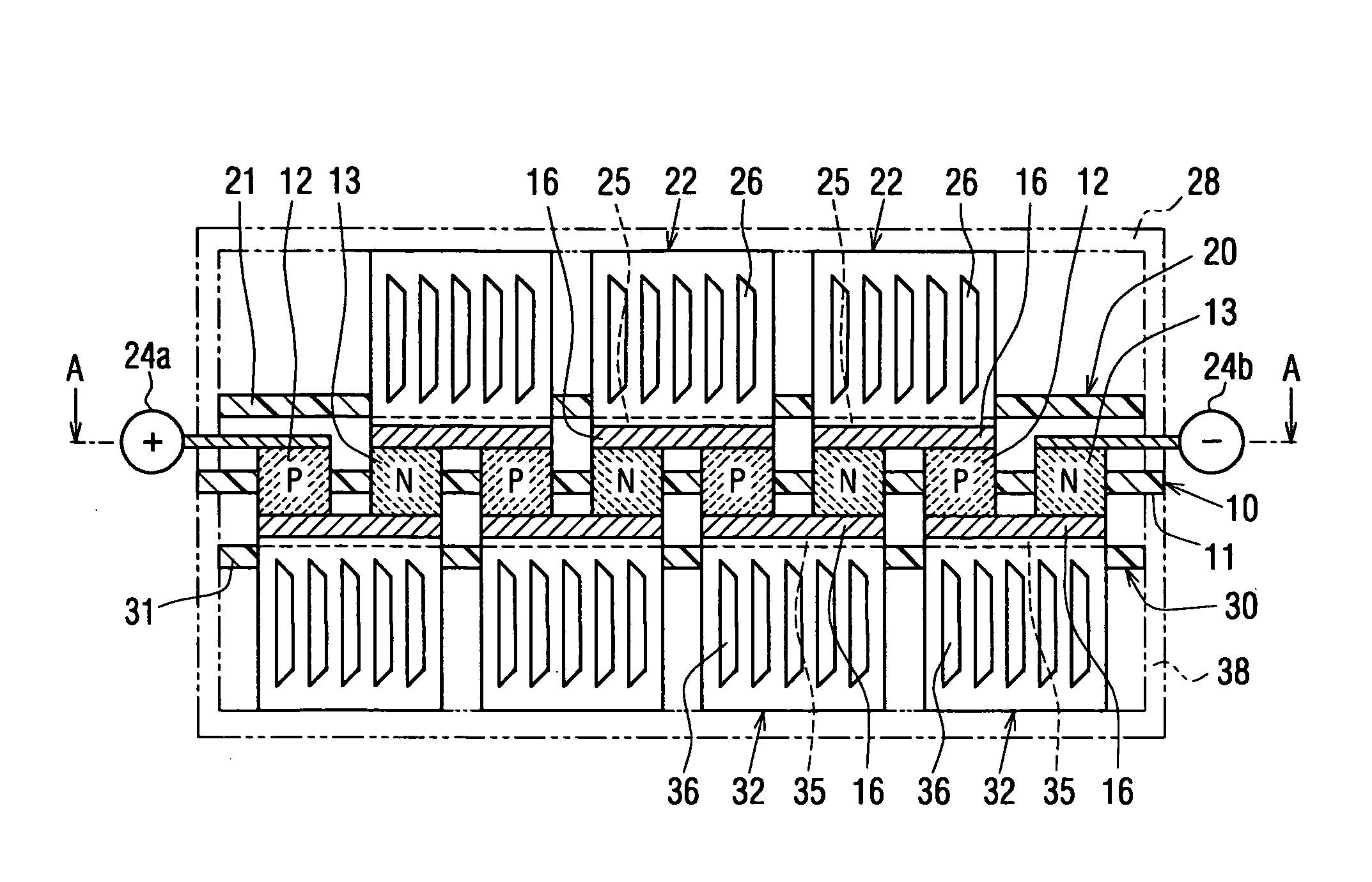
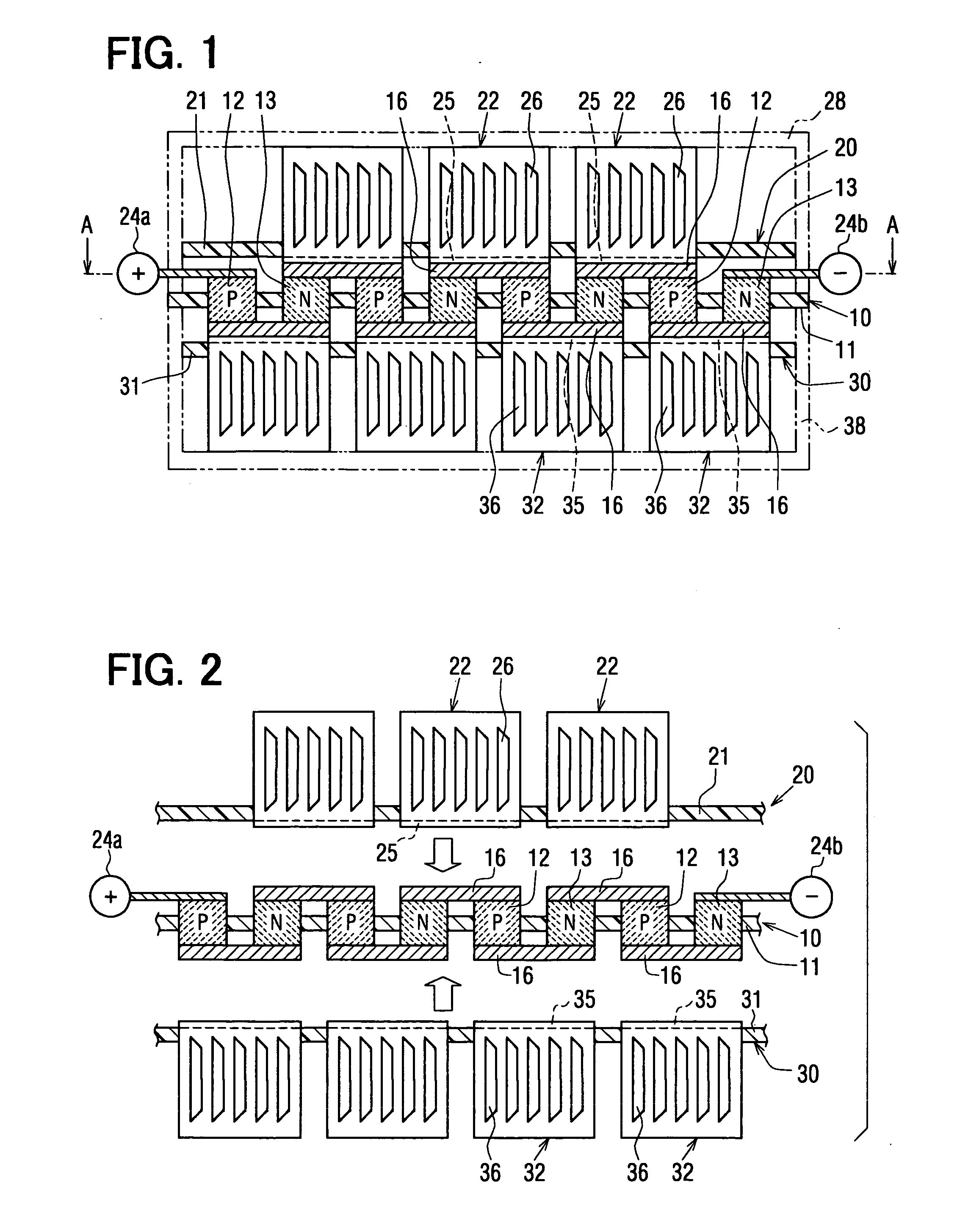
[0279]FIG. 17 and FIG. 18 illustrate a tenth embodiment according to the present invention. In this embodiment, the P-type thermoelectric elements 12 and the N-type thermoelectric elements 13 are pre-placed on either the heat-absorbing electrodes 25 or the heat-dissipating electrodes 35 to form a plurality of units, and the plurality of the units are arranged to form a thermoelectric converter.

[0280] The heat-absorbing electrode substrate 20 has the first heat-absorbing electrode members 22. Each of the first heat-absorbing electrode members 22 has a flat-plate-shaped heat-absorbing electrode 25 and a heat-absorbing heat-exchange member 22a which is thermally connected to the heat-absorbing electrode 25 for heat exchange with air. The heat-absorbing electrode 25 is fixed to one face of a second insulating substrate 21. The heat-absorbing heat-exchange member 22a is shaped in bracket form. Two arms of the heat-absorbing heat-exchange member 22a extend through the second insulating s...

eleventh embodiment

[0287]FIG. 19 illustrates an eleventh embodiment. In this embodiment, the first heat-absorbing electrode members 22 and the first heat-dissipating electrode members 32 are fitted to the thermoelectric element substrate 10.

[0288] Convex portions 11a, 11b are formed as protrusions from the two faces of the first insulating substrate 11 between the P-type thermoelectric element 12 and the N-type thermoelectric element 13 which are adjacent to each other. Receiving portions 25b, 35b into which the convex portions 11b are fitted are formed in the heat-absorbing electrode 25 and the heat-dissipating electrode 35. The fitting portions 25b, 35b are fitted over the convex portions 11b. The thermoelectric element substrate 10 is situated so as to be sandwiched between the first heat-absorbing electrode members 22 and the first heat-dissipating electrode members 32. It should be noted that the convex portion 11a is a convex portion electrically insulating the first heat-absorbing electrode me...

twelfth embodiment

[0290]FIG. 20 to FIG. 22 illustrate a twelfth embodiment according to the present invention. In this embodiment, the first heat-absorbing electrode member 22 is provided by coupling a plurality of members together. A similar structure is used for the first heat-dissipating electrode member 32. The structure of this embodiment may be used for either the first heat-absorbing electrode member 22 or the first heat-dissipating electrode member 32. The first heat-absorbing electrode member 22 will be described below and the corresponding parts of the first heat-dissipating electrode member 32 are indicated by parenthetical reference numerals.

[0291] The first heat-absorbing electrode member 22 (32) is formed by joining two second heat-absorbing electrode members 221 (321) and a third heat-absorbing electrode member 222 (322) together. The second heat-absorbing electrode members 221 (321) and the third heat-absorbing electrode member 222 (322) differ from each other in the length of a heat...


PUM


Abstract

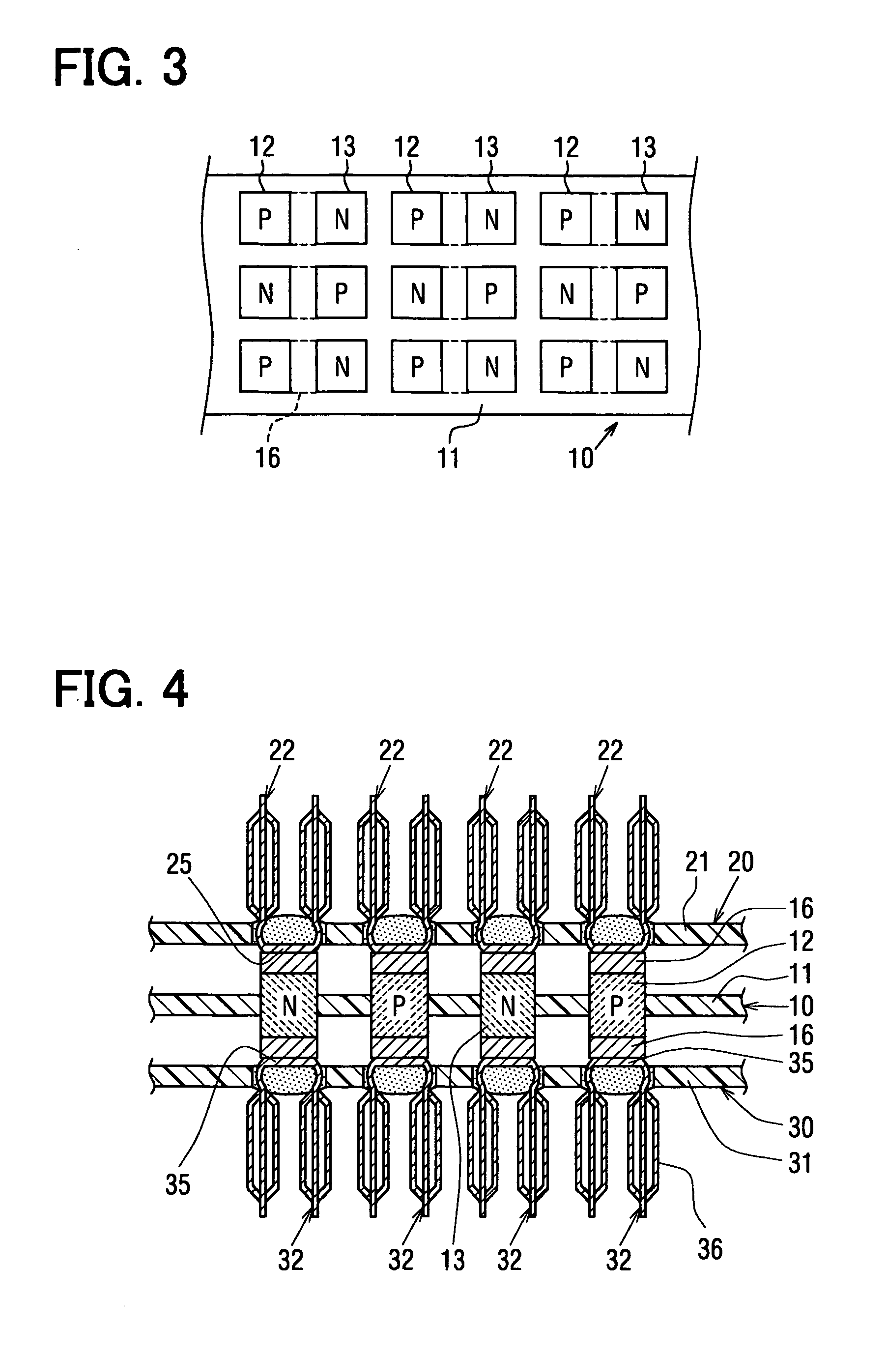
A thermoelectric converter comprises a thermoelectric element assembly that includes a plurality of P-type thermoelectric elements and a plurality of N-type thermoelectric elements which are arranged in a predetermined arrangement pattern; and a heat-exchange element assembly provided with a plurality of heat exchange elements and a retaining plate retaining the plurality of the heat exchange elements, the plurality of the heat exchange elements being retained in a predetermined arrangement condition corresponding to a arrangement condition of the thermoelectric elements. Then, a plurality of joining sites between the thermoelectric element assembly and the heat-exchange element assembly are all together joined by joining members in a state in which the thermoelectric element assembly and the heat-exchange element assembly are stacked on each other.

Description

FIELD OF THE INVENTION [0001] This invention relates to a thermoelectric converter having N-type thermoelectric elements and P-type thermoelectric elements connected in series. BACKGROUND ART [0002] There are conventionally known thermoelectric converters disclosed in Japanese Patent Publication No. 3166228 (U.S. Pat. No. 5,254,178), Japanese Unexamined Patent Publication No. H5-175556, and U.S. Pat. No. 6,521,991. [0003] In the above conventional art, a plurality of N-type thermoelectric elements and a plurality of P-type thermoelectric elements are alternately connected in series. These junctions are lowered or increased in temperature by the Peltier effect depending on the direction of the current passage. The low-temperature area is called a heat-absorbing area or cooling area, and the high-temperature area is called a heat-dissipating area or heating area. The conventional art discloses further the structure in which a member for facilitating heat exchange is mounted on the jun...

Claims


Application Information

Patent Timeline
Patent Type & Authority Applications(United States)
IPC IPC(8): F25B21/02H01L35/30H10N10/13H01L23/38H02N11/00H10N10/17H10N10/852
CPCH01L35/32H01L35/30H10N10/17H10N10/13
Inventor MATSUOKA, AKIOKUROYANAGI, ISAOYAMAMOTO, TAKASHIHATANO, YUKINORIUTO, MAKOTONIIMI, YASUHIKOYOSHINO, HIROKAZUNAKAMURA, FUMIAKIMIZUTANI, SATOSHIEBIHARA, JIRO
Owner DENSO CORP
Learn More