Headlight, Taillight And Streetlight Detection

a technology of headlights and streetlights, applied in the direction of optical radiation measurement, instruments, transportation and packaging, etc., can solve the problems of affecting the performance affecting the maintenance time of the other control system which rely on the same, and half or more of the (possibly critical) frames may not be available for the other control system

Active Publication Date: 2007-09-27
MOBILEYE VISION TECH LTD
View PDF16 Cites 157 Cited by
  • Summary
  • Abstract
  • Description
  • Claims
  • Application Information

AI Technical Summary

Benefits of technology

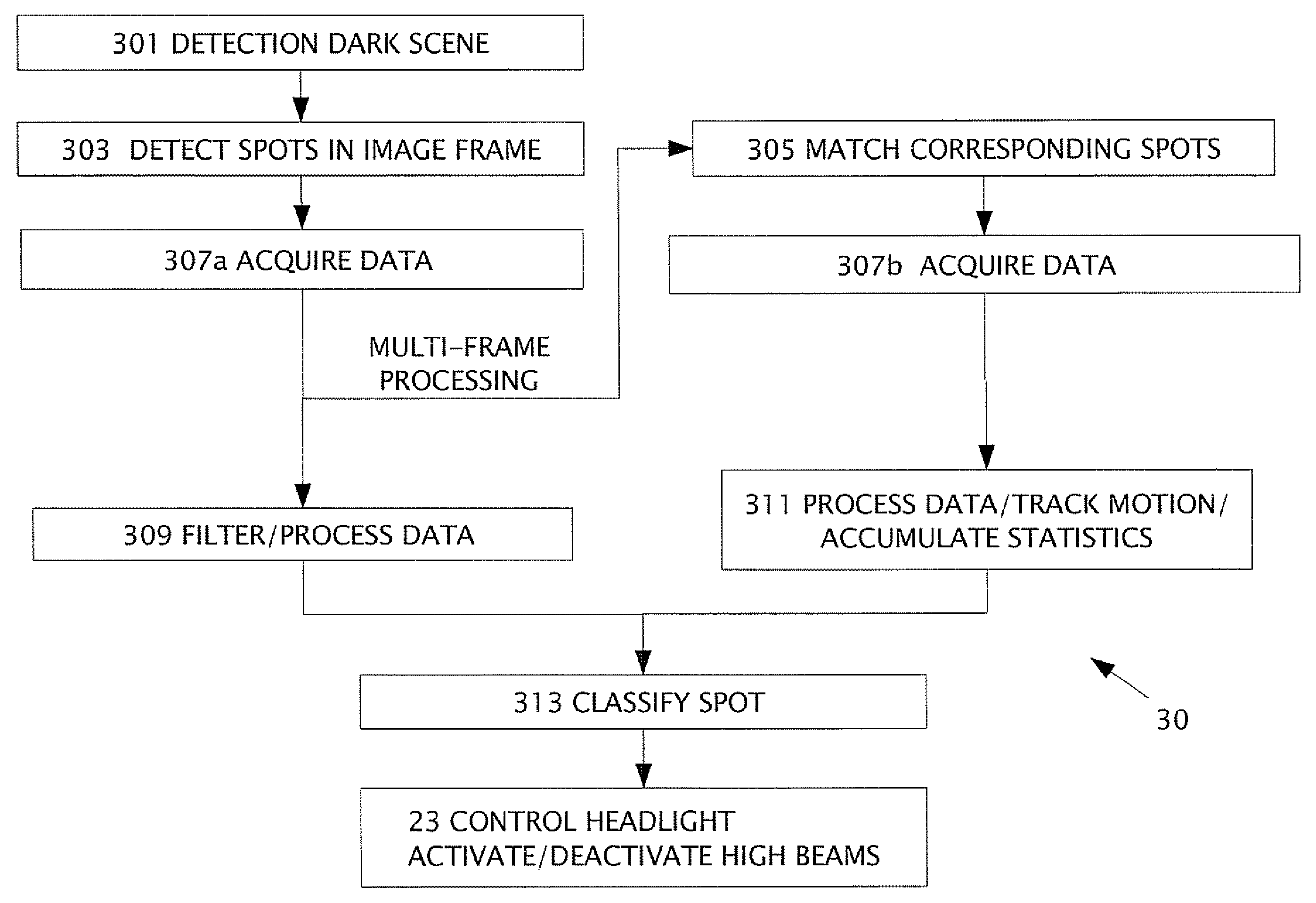
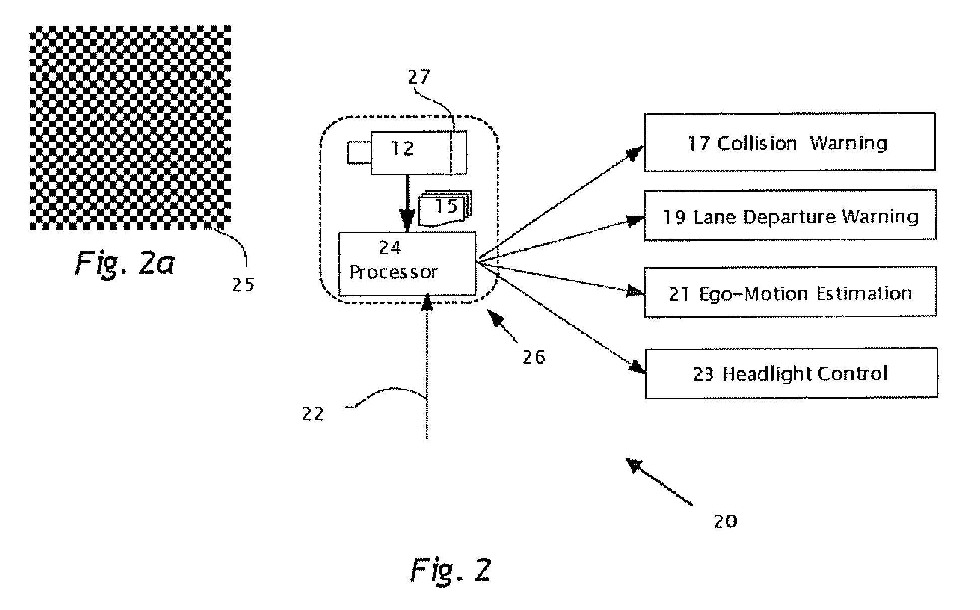
[0016]According to the present invention there is provided a method in a computerized system including an image sensor mounted in a moving vehicle. The image sensor captures image frames consecutively in real time. In one of the image frames, a spot is detected of measurable brightness; the spot is matched in subsequent image frames. The spot and the corresponding spot are images of the same object. The object is typically one or more of headlights from an oncoming vehicle, taillights of a leading vehicle, streetlights, street signs and/or traffic signs. Data is acquired from the spot and from the corresponding spot. By processing the data, the object (or spot) is classified producing an object classification. Substantially all the image frames are available to the computerized vehicle control system and at least one other vehicle control system. The vehicle control system controls preferably headlights of the moving vehicle based on the object classification. The other vehicle control system using the image frames is one or more of: lane departure warning system, collision warning system and/or ego-motion estimation system. The object classification is typically provided to and used by one or more of the other vehicle control systems. The data typically relates to a property of the spot and the corresponding spot, such as position in the image frame, shape, brightness, motion, color and spatial alignment. The motion of the spot is tracked (in image space) by comparing respective image frame positions of the spot and the corresponding spot. Spots can be classified using radial basis functions. The spots are classified as headlights, taillights, street lights, or road signs. Street lights are preferably classified using spatial alignment. Preferably, classification is performed using texture and/or edge characteristics of the spots. For each of the spots, the classification uses the data from an area centered on each spot including N×N picture elements of the image frame, wherein N is an integer preferably less than twenty.
[0017]Typically, the object is not classified as a street sign when the motion is outward and upward. High beams are deactivated upon classifying the object as being a part of a vehicle such as a passing vehicle, a preceding vehicle or an oncoming vehicle. The high beams are reactivated based on the tracking motion. Preferably, the data is related to a shape of the spot, wherein the shape is indicative of the spot splitting into spots in one or more subsequent image frames. A second spot of measurable brightness is preferably detected in the first image frame; and motion is tracked of the spot and the second spot between the first image frames and one or more subsequent image frames. The first and second spots are paired based on comparing the motion of the first spot to motion of the second spot. The object is classified as a taillight when the motion of the first and second spot is inward. Compensation of the motion, e.g. yaw and/or pitch of the vehicle is preferable prior to classification based on motion of the first and second spots.
[0018]According to the present invention there is provided a method for contr...

Problems solved by technology

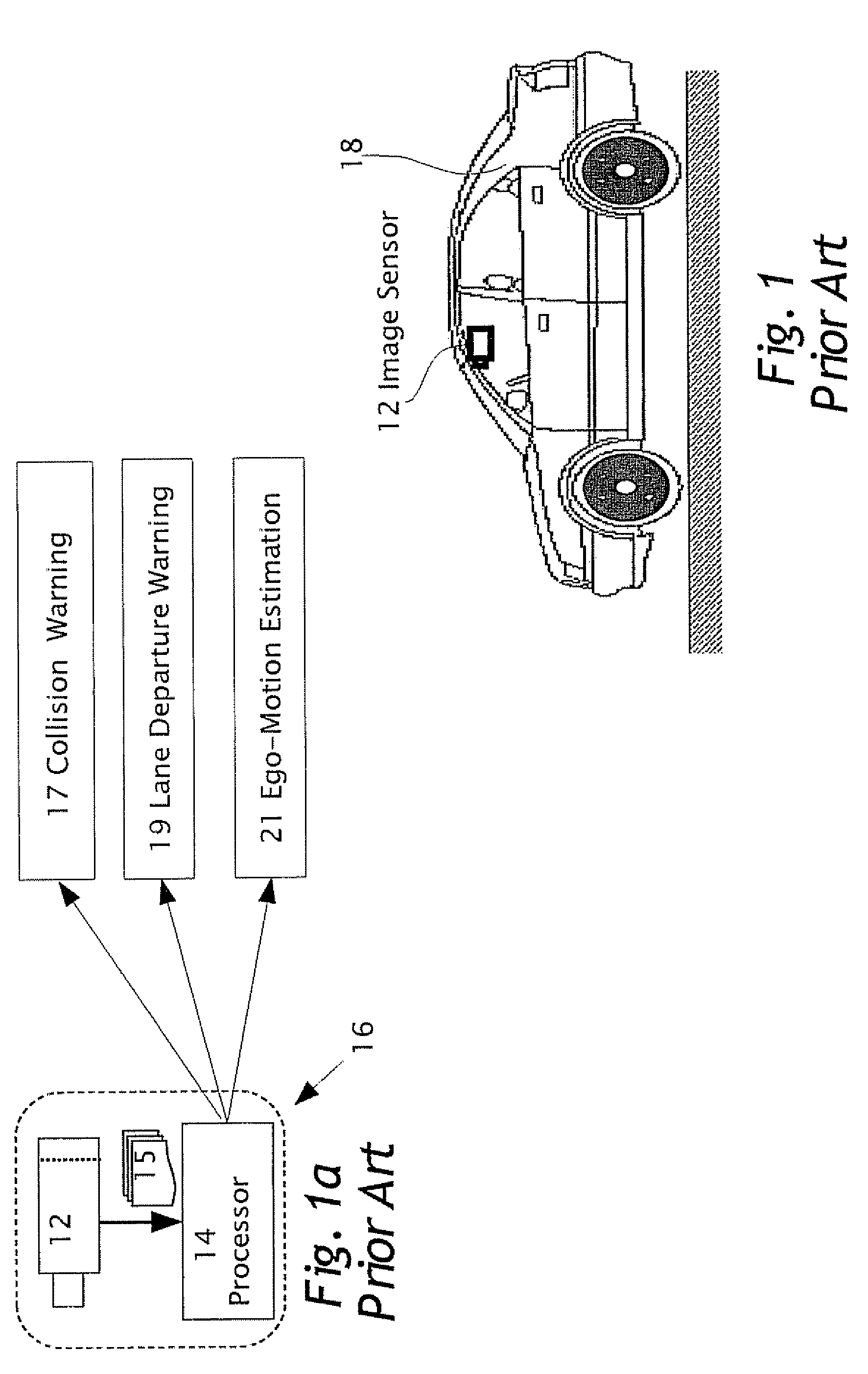
Vehicle control systems, such as disclosed in U.S. Pat. No. 6,831,261 which rely on changing exposure parameters (ie, aperture, exposure, magnification, etc) in order to detect headlights have a difficult time maintaining other control systems which rely on the same camera, e.g. Lane Departure Warning, Forward Collision Warning, etc.
As a result of changing exposure parameters half or more of the (possibly critical) frames may not be available for the other control systems.
This greatly affects performance of the other control systems.
Additionally, the use of color cameras with infrared filters req...

Method used


Image

  • Headlight, Taillight And Streetlight Detection
  • Headlight, Taillight And Streetlight Detection
  • Headlight, Taillight And Streetlight Detection

Examples


Embodiment Construction

[0033]The present invention is of a system and method for detecting and classifying objects in real time, e.g. oncoming vehicle headlights, leading vehicle taillights and streetlights, in a series of image frames 15 obtained from a camera mounted on an automobile to provide a signal for switching the headlights between high beams and low beams, specifically with image frames 15 available for use by other vehicle control applications

[0034]The principles and operation of a system and method of detecting and classifying objects in real time, in a series of images obtained from a camera mounted on an automobile to provide a signal for switching the headlights between high beams and low beams, according to the present invention, may be better understood with reference to the drawings and the accompanying description.

[0035]Before explaining embodiments of the invention in detail, it is to be understood that the invention is not limited in its application to the details of design and the a...


PUM


Abstract

A method in a computerized system including an image sensor mounted in a moving vehicle. The image sensor captures image frames consecutively in real time. In one of the image flames, a spot is detected of measurable brightness; the spot is matched in subsequent image frames. The image frames are available for sharing between the computerized system and another vehicle control system. The spot and the corresponding spot are images of the same object. The object is typically one or more of headlights from an oncoming vehicle, taillights of a leading vehicle, streetlights, street signs and/or traffic signs. Data is acquired from the spot and from the corresponding spot. By processing the data, the object (or spot) is classified. producing an object classification. The vehicle control system controls preferably headlights of the moving vehicle based on the object classification. The other vehicle control system using the image frames is one or more of: lane departure warning system, collision warning system and/or ego-motion estimation system.

Description

CROSS REFERENCE TO RELATED APPLICATIONS[0001]The present application claims the benefit under 35 USC 119(e) of U.S. provisional application 60 / 785,351 filed on Mar. 24, 2006, and 60 / 836,670 filed Aug. 10, 2006, the disclosures of which are incorporated herein by reference.FIELD AND BACKGROUND OF THE INVENTION[0002]The present invention relates to vehicle control systems in vehicles, Specifically, the present invention detects and classifies objects in real time, e.g. oncoming vehicle headlights, leading vehicle taillights and streetlights, in a series of images obtained from a camera mounted on a vehicle, The images are used in parallel by a number of vehicle control systems including lane departure detection, forward collision control and headlight control systems. The classification of objects is preferably used by more than one of the vehicle control systems. In a headlight control system, the classification of objects is used to provide a signal for switching the headlights betw...

Claims


Application Information

Patent Timeline
IPC IPC(8): G01J1/32
CPCB60Q1/143B60Q2300/3321B60Q2300/41B60Q2300/42G06K9/00825G06K9/00818G08G1/16G08G1/167B60Q2300/45G08G1/165G08G1/166G06V20/582G06V20/584
Inventor STEIN, GIDEON P.HADASSI, OFERBEN HAIM, NOAMWOLFOVITZ, URI
Owner MOBILEYE VISION TECH LTD
Why Eureka
Try Eureka