Systems and methods for enhancing the magnetic coupling in a wireless communication system

a wireless communication system and magnetic coupling technology, applied in the field of radio frequency communication systems, can solve the problems of limited operational range, inability to overcome problems, and inability to use conventional range extenders, etc., to achieve the effect of improving communication

Active Publication Date: 2007-09-27
MACRONIX INT CO LTD
View PDF9 Cites 43 Cited by
  • Summary
  • Abstract
  • Description
  • Claims
  • Application Information

AI Technical Summary

Benefits of technology

[0014] An RFID system comprises an intermediate device that includes a first and second antenna coils connected together in a close loop format. The coils are formed on a flexible substrate that can be folded around a magnetic flux blocker such that one loop is on side of the blocker and the other loop is on the other side of the blocker. The intermediate device can then improve communication between a reader on one side of the blocker and a tag on the other. The coil on the reader side of the blocker can receive RF signals being generated by the reader and convert them to an electrical signal that can be passed to the coil on the tag side of the blockage. The second coil can then generate an RF signal that can be transmitted to the tag.

Problems solved by technology

While passive tags provide many benefits that make them increasingly more popular for new RFID applications, one drawback is the limited operational range, e.g., as compared to active tags.
Conventional range extenders do not necessarily help, however, when the limited range is due to some impediment to the RF signal being produced by the reader.
When limited communication range is the result of a magnetic flux blocker, a range extender will not necessarily overcome the problem.
Accordingly, communication range can be limited for many of these new applications.
Unfortunately, conventional range extenders will not necessarily be able to overcome some of the limited communication ranges for these new applications.

Method used


Image

  • Systems and methods for enhancing the magnetic coupling in a wireless communication system
  • Systems and methods for enhancing the magnetic coupling in a wireless communication system
  • Systems and methods for enhancing the magnetic coupling in a wireless communication system

Examples


Embodiment Construction

.”

BRIEF DESCRIPTION OF THE DRAWINGS

[0018] Features, aspects, and embodiments of the inventions are described in conjunction with the attached drawings, in which:

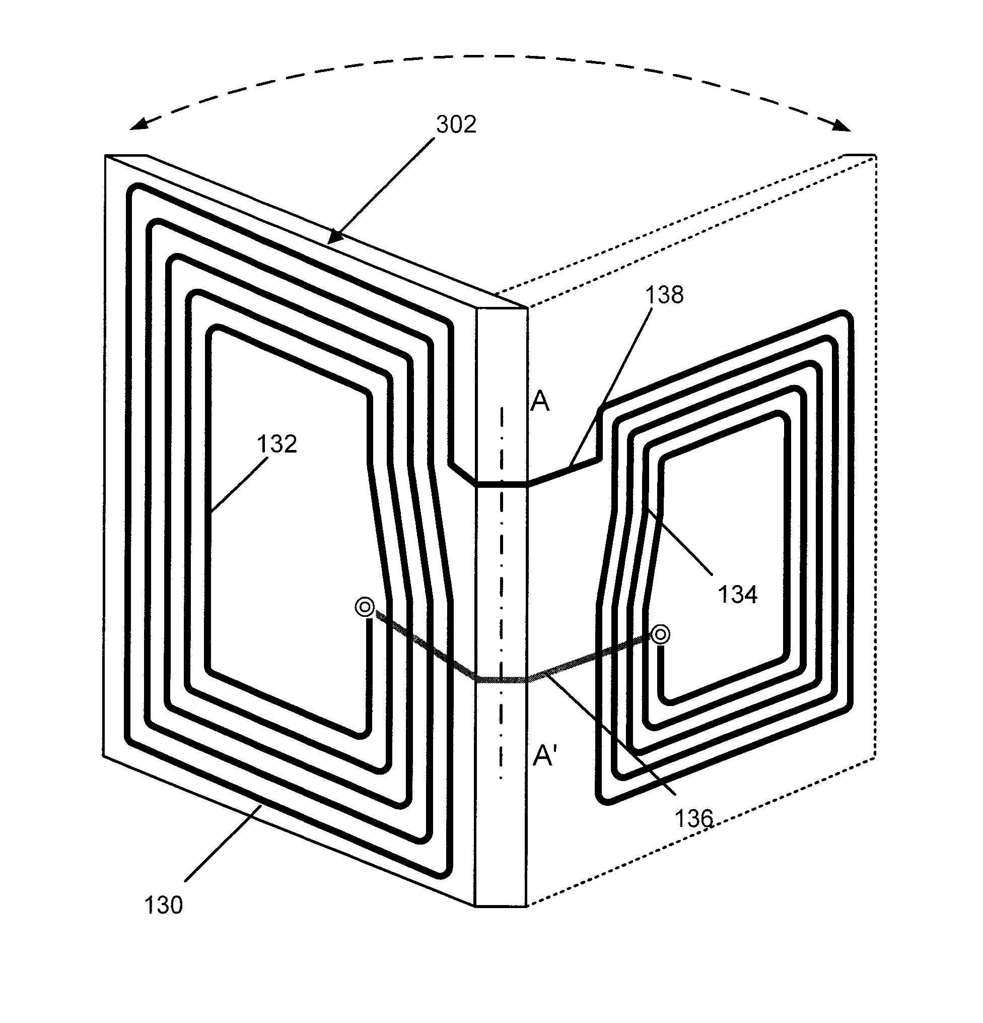
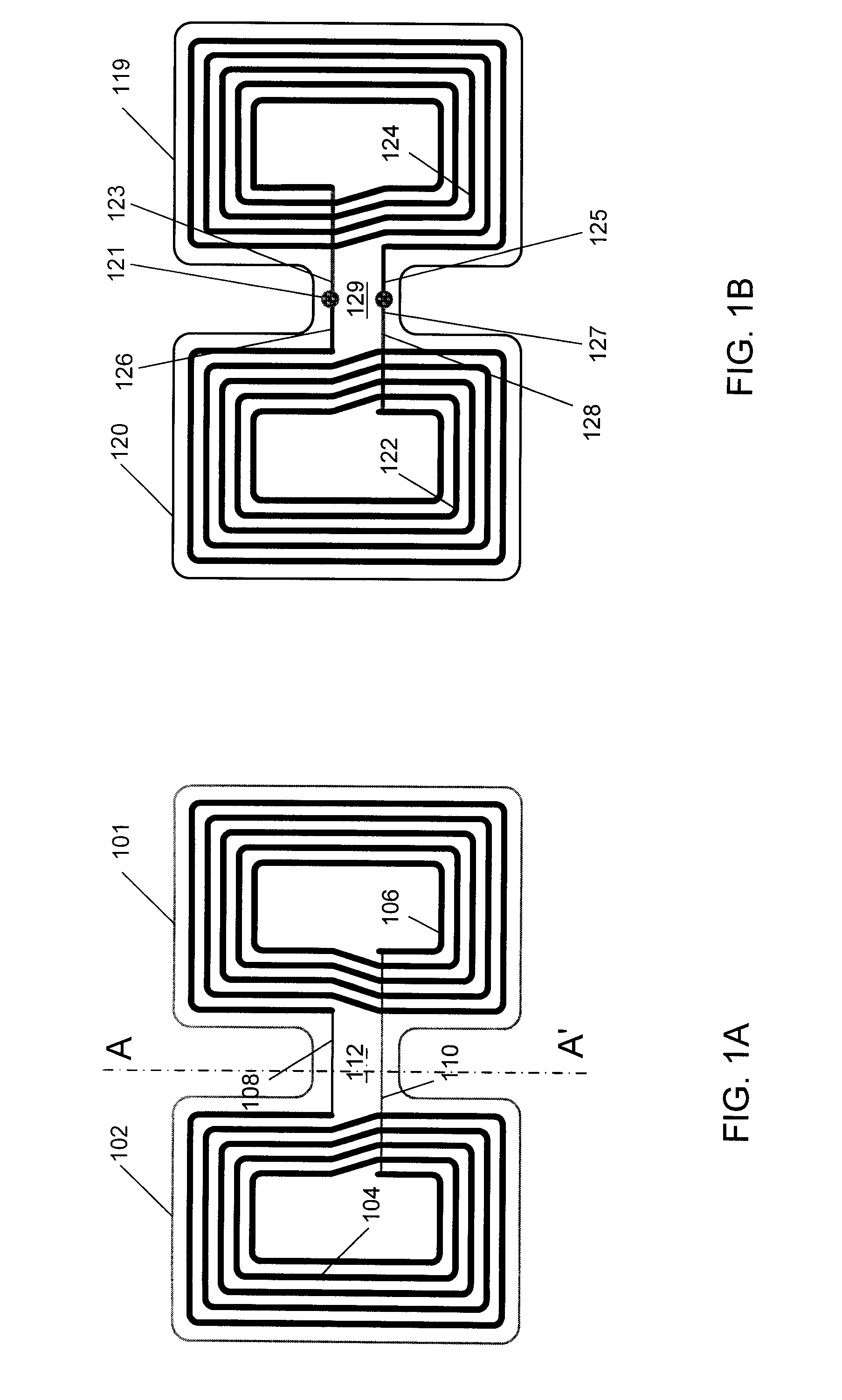
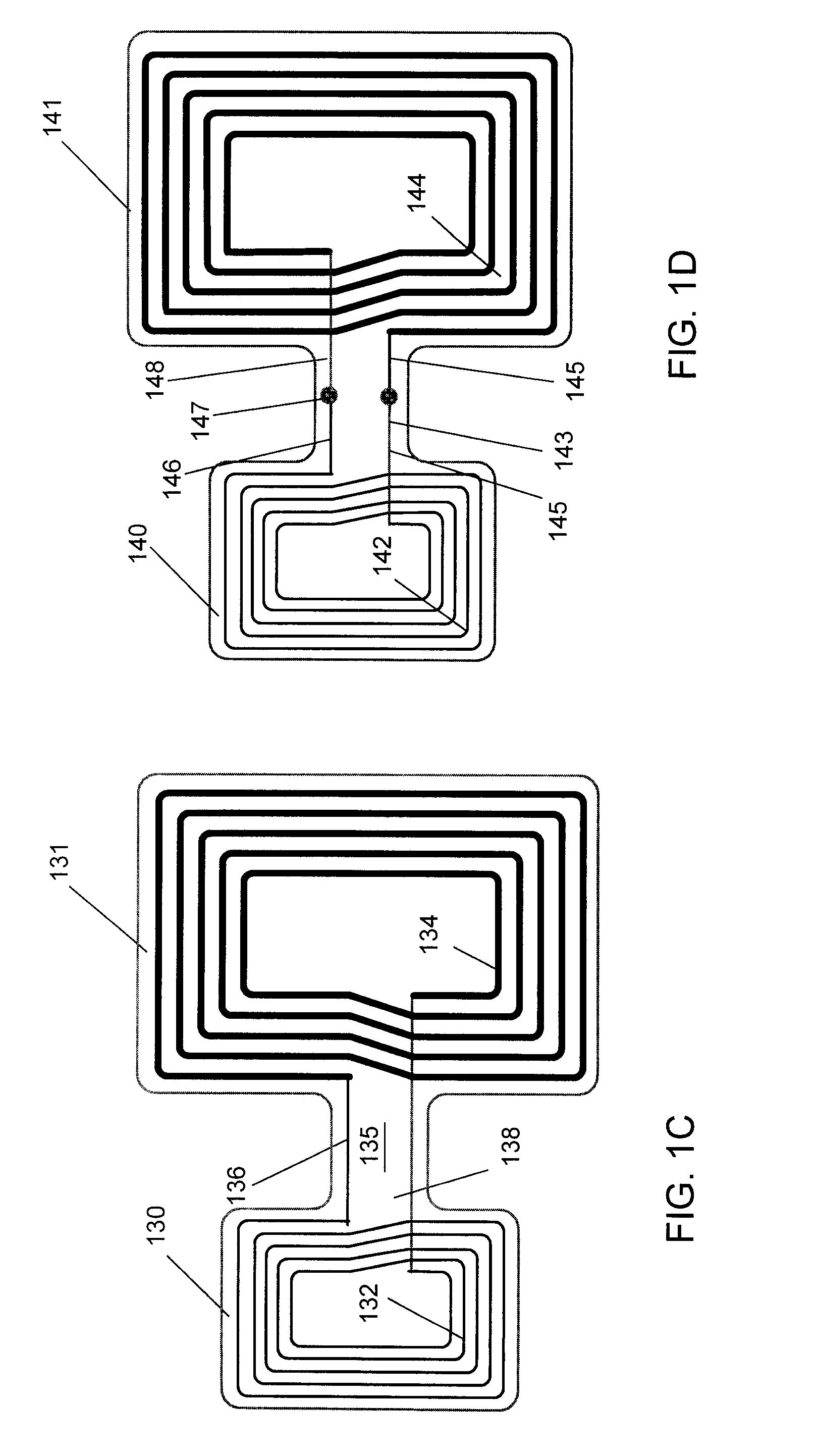
[0019]FIGS. 1A-1D are diagrams illustrating example embodiments of intermediate antennas configured in accordance with different embodiments;

[0020]FIG. 2 is a diagram illustrating one of the antennas of FIGS. 1A-1D;

[0021]FIG. 3 is a diagram illustrating the antenna of FIG. 2 formed around a magnetic flux blocker;

[0022]FIG. 4 is a diagram illustrating an RFID system comprising the intermediate antenna of FIG. 2 in accordance with one embodiment; and

[0023]FIG. 5 is a diagram illustrating a mobile communication device comprising an intermediate antenna in accordance with one embodiment.

DETAILED DESCRIPTION

[0024] The embodiments described below are generally directed to RFID systems and devices; however, it will be understood that the systems and methods described herein can apply to other types of RF communication system...


PUM


Abstract

An RFID system comprises an intermediate device that includes a first and second antenna coils connected together in a close loop format. The coils are formed on a flexible substrate that can be folded around a magnetic flux blocker such that one loop is on side of the blocker and the other loop is on the other side of the blocker. The intermediate device can then improve communication between a reader on one side of the blocker and a tag on the other. The coil on the reader side of the blocker can receive RF signals being generated by the reader and convert them to an electrical signal that can be passed to the coil on the tag side of the blockage. The second coil can then generate an RF signal that can be transmitted to the tag.

Description

BACKGROUND [0001] 1. Field of the Invention [0002] The embodiments described herein are directed to radio frequency communication systems, and more particular to systems and methods for extending the communication range in a radio frequency communication system. [0003] 2. Background of the Invention [0004] Radio Frequency Identification (RFID) systems are a type of radio frequency communication system. RFID systems are gaining attention due to their ability to track and identify moving objects. In an RFID system, remote objects intended to be tracked and identified are equipped with a small RFID tag. The RFID tag contains a transponder and a digital memory chip that is given a unique electronic identification. An interrogator, or a reader can be configured to emit a signal that can activate the RFID tag. When an RFID tag passes within range of the reader, the RFID tag can detect the reader's signal and provide its identification information. The reader can be configured to decode th...

Claims


Application Information

Patent Timeline
Patent Type & Authority Applications(United States)
IPC IPC(8): G08B13/14
CPCG06K7/10178H01Q1/2208G06K7/10336
Inventor LUO, HUAN-CHINCHIANG, LU-SHANLO, YING-CHESHEN, CHIA-JUILAI, PO-CHIHLEE, KUNG-HUA
Owner MACRONIX INT CO LTD
Why Eureka
Try Eureka