RFID tag

Inactive Publication Date: 2007-09-27
NEC CORP
View PDF0 Cites 53 Cited by
  • Summary
  • Abstract
  • Description
  • Claims
  • Application Information

AI Technical Summary

Benefits of technology

[0009]The present invention has been made to solve this problem, and has as its objective to provide an RFID

Problems solved by technology

Since RFID technique allows contactless access to tag memory, it is possible that a malicious user reads/rewrites data from/in the RFID tag without letting the owner or authorized user of the RFID tag consent to or notice it.
This may pose serious problems in terms of privacy protection and information security.
Since RFID using UHF band allows access to memory of an RFID t

Method used


Image

  • RFID tag
  • RFID tag
  • RFID tag

Examples


first embodiment

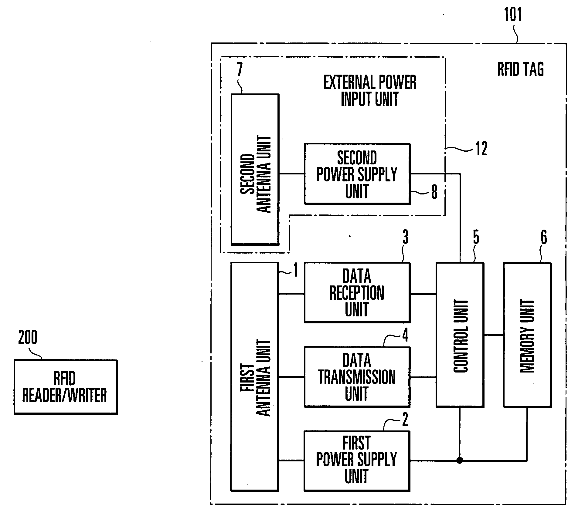
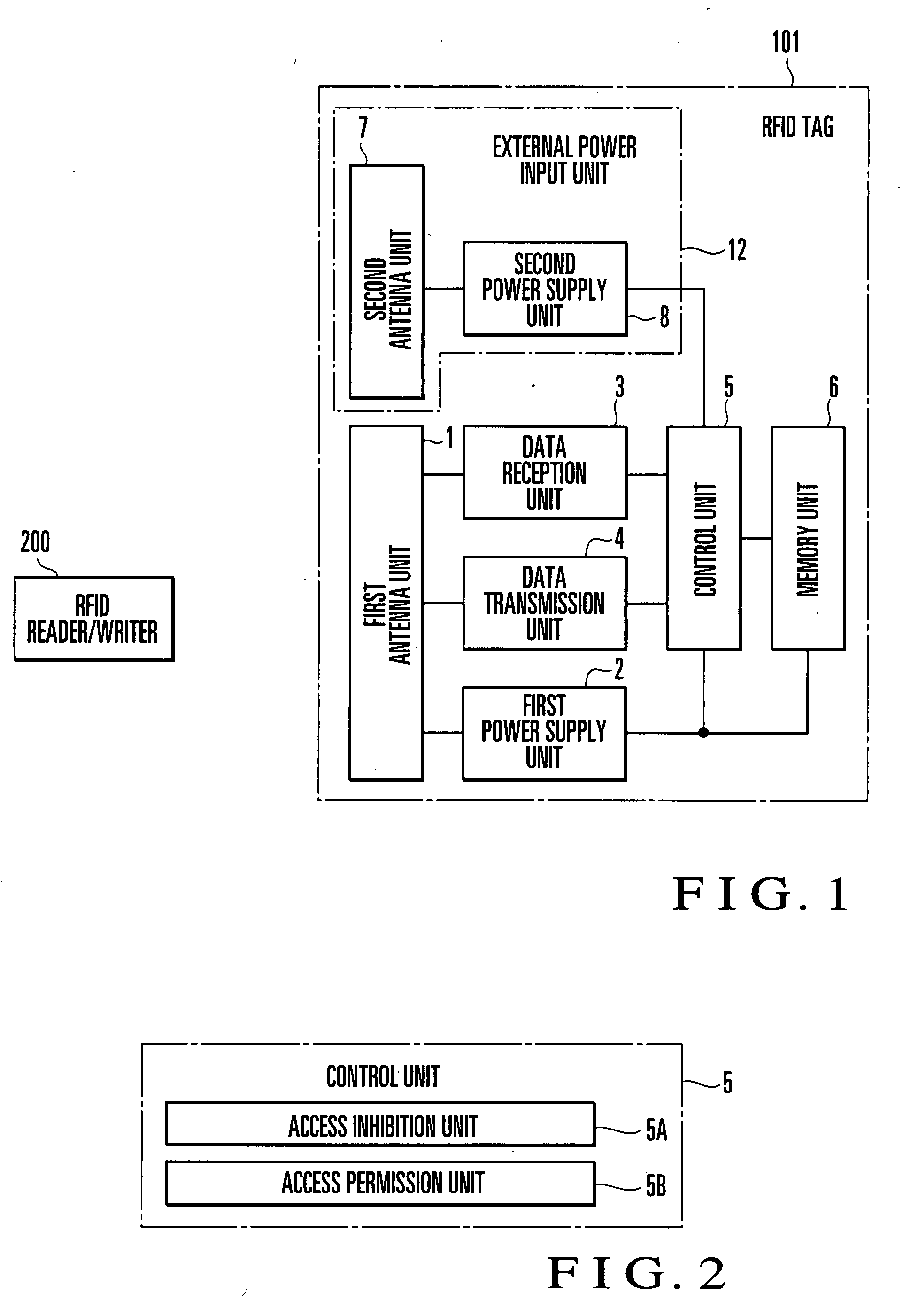
[0042]FIG. 1 shows the schematic arrangement of an RFID tag according to the first embodiment of the present invention. As shown in FIG. 1, an RFID tag 101 according to the first embodiment comprises a first antenna unit 1 which transmits / receives radio waves to / from an RFID reader / writer 200, a first power supply unit 2 which extracts power from the radio wave received by the first antenna unit 1, a data reception unit 3 which decodes a command contained in the radio wave received by the first antenna unit 1 and transmits the resultant data to a control unit 5, a data transmission unit 4 which encodes the return data transmitted from the control unit 5 in a transmission radio wave from the first antenna unit 1, the control unit 5 which interprets the command contained in the radio wave received by the first antenna unit 1 and accesses a memory unit 6, the memory unit 6 which stores an ID, user data, and the like and an external power input unit 12 which inputs external power. The e...

second embodiment

[0056]The RFID tag 101 shown in FIG. 1 is configured such that the first antenna unit 1 and the second antenna unit 7 use the same frequency band for communication. However, the frequency band of the first antenna unit 1 may differ from that of the second antenna unit 7, and the RFID tag 101 may include another radio wave source to the second antenna unit 7.

[0057]For example, as shown in FIG. 6, the frequency band of a first antenna unit 1 is made to differ from that of a second antenna unit 7, and a radio wave source 300 is provided for the second antenna unit 7 independently of an RFID reader / writer 200.

[0058]According to an RFID tag 10′, when the radio wave source 300 is located within a communicable distance L2 of the second antenna unit 7, the second antenna unit 7 receives a radio wave from the radio wave source 300. Since the power of the received radio wave is sufficiently high for the reception sensitivity of the second antenna unit 7, and hence a second power supply unit 8...

third embodiment

[0060]In the first embodiment, all the data stored in the memory unit 6 are protected from malicious access. However, it is conceivable that some data require no protection depending on the type of data. The third embodiment, therefore, sets only data requiring protection as a target for unauthorized access prevention by switching memory units for storage depending on the type of data, thereby further improving the convenience in using data.

[0061]FIG. 8 shows the schematic arrangement of an RFID tag according to the third embodiment of the present invention. An RFID tag 102 of the third embodiment has an arrangement in which a memory unit 6 is divided into a protected memory unit 6A and an unprotected memory unit 6B. The protected memory unit 6A stores data which need protection. The unprotected memory unit 6B stores data which do not need protection. A control unit 5 comprises two functional units, i.e., an access inhibition unit 5C which inhibits access from an RFID reader / writer ...


PUM


Abstract

An RFID tag includes an external power input unit, first antenna unit, first power supply unit, memory unit, and control unit. The external power input unit inputs external power. The first antenna unit receives power from a communication device. The first power supply unit extracts power from the radio wave received by the first antenna unit. The control unit operates upon receiving power from the first power supply unit and controls permission and inhibition of access from the communication device to the memory unit in accordance with presence/absence of input of power from the external power input unit.

Description

BACKGROUND OF THE INVENTION[0001]The present invention relates to an RFID (Radio Frequency Identification) tag which performs data communication with a communication device such as a reader or a reader / writer through radio waves.[0002]Recently, RFID has rapidly become popular as an automatic identification technique using radio communication. A general RFID system comprises an RFID tag, which is attached to an article to identify it, and a reader / writer (RFID reader / writer), which is used to read out data stored in a memory in the RFID tag or write data in the memory in the RFID tag.[0003]One of the features of RFID technique is contactless access to tag memory. This feature makes it possible to read / write data from / in tag memory even when multiple articles, each of which is attached an RFID tag, are packed in a box without unpacking it. This technique can improve the efficiency of various business processes such as article receiving and shipping, and hence is expected to be applied...

Claims


Application Information

Patent Timeline
IPC IPC(8): G08B13/14
CPCG06K19/07336
Inventor TAGATO, HIROKI
Owner NEC CORP
Why Eureka
Try Eureka