Interlockable watchwinder

a watchwinder and lockable technology, applied in the field of watchwinders, can solve the problems of affecting the quality of watch winding, the energy in the mainspring tends to run down or completely dissipate, and the self-winding watch generally cannot be fully rewound in a few seconds, and achieves considerable flexibility and is easy to assemble and disassemble.

Active Publication Date: 2007-09-27
WOLF 1834
View PDF38 Cites 22 Cited by
  • Summary
  • Abstract
  • Description
  • Claims
  • Application Information

AI Technical Summary

Benefits of technology

[0011] Briefly, and in general terms, the present invention provides a universal watchwinder construction which is useable individually or as part of a re-configurable and customizable grouping of interconnected watchwinders. The groupings are relatively easy to assemble and disassemble, with only a minimum variety of basic components, and have considerable flexibility in terms of size...

Problems solved by technology

When the watch is worn, the random movements of the wearer cause the pendulum to oscillate back and forth, or to spin completely about its axis, thereby winding the mainspring of the watch movement.
However, it will be appreciated that when the watch is not being worn for a sufficiently long period of time, the energy in the mainspring will tend to run down or completely dissipate.
Once the spring is unwound, a self-winding watch generally cannot be fully rewound in a few seconds.
The task of rewinding a self-winding watch can be a major inconvenience, as it may include resetting the time, dates and numerous other functions, or “complications,” each time the spring runs down.
The task becomes even more cumbersome when multiple watches are involved.
While compact, unobtrusive and easy to move and store, these single rotator watchwinders are limited to use with one watch at a time.
The end user lacks flexibility to change the pre-arranged configuration of rotators within the housing or to selectively remove one or more rotators from the housing for independent use.
Moreover, the additional size and weight of these multiple rotator watchwinders makes them more difficult to move or store.
However, these systems are not convenient for the collector or user who has an ever-growing collection of watches (and thus constantly finds himself with a shortage of rotator capacity).
They also are not convenient for the collector or user who has a need f...

Method used


Image

  • Interlockable watchwinder
  • Interlockable watchwinder
  • Interlockable watchwinder

Examples


Embodiment Construction

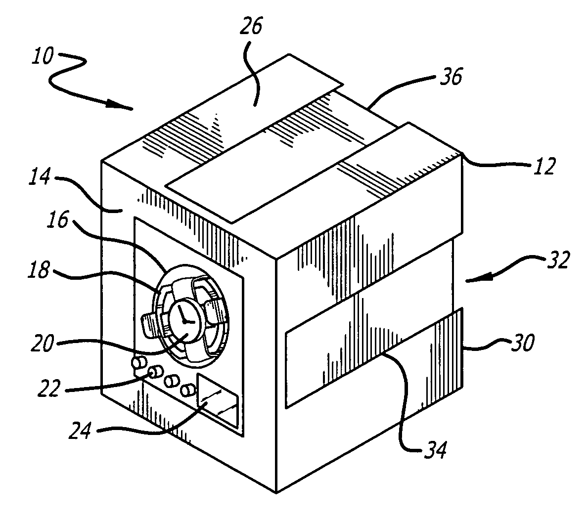
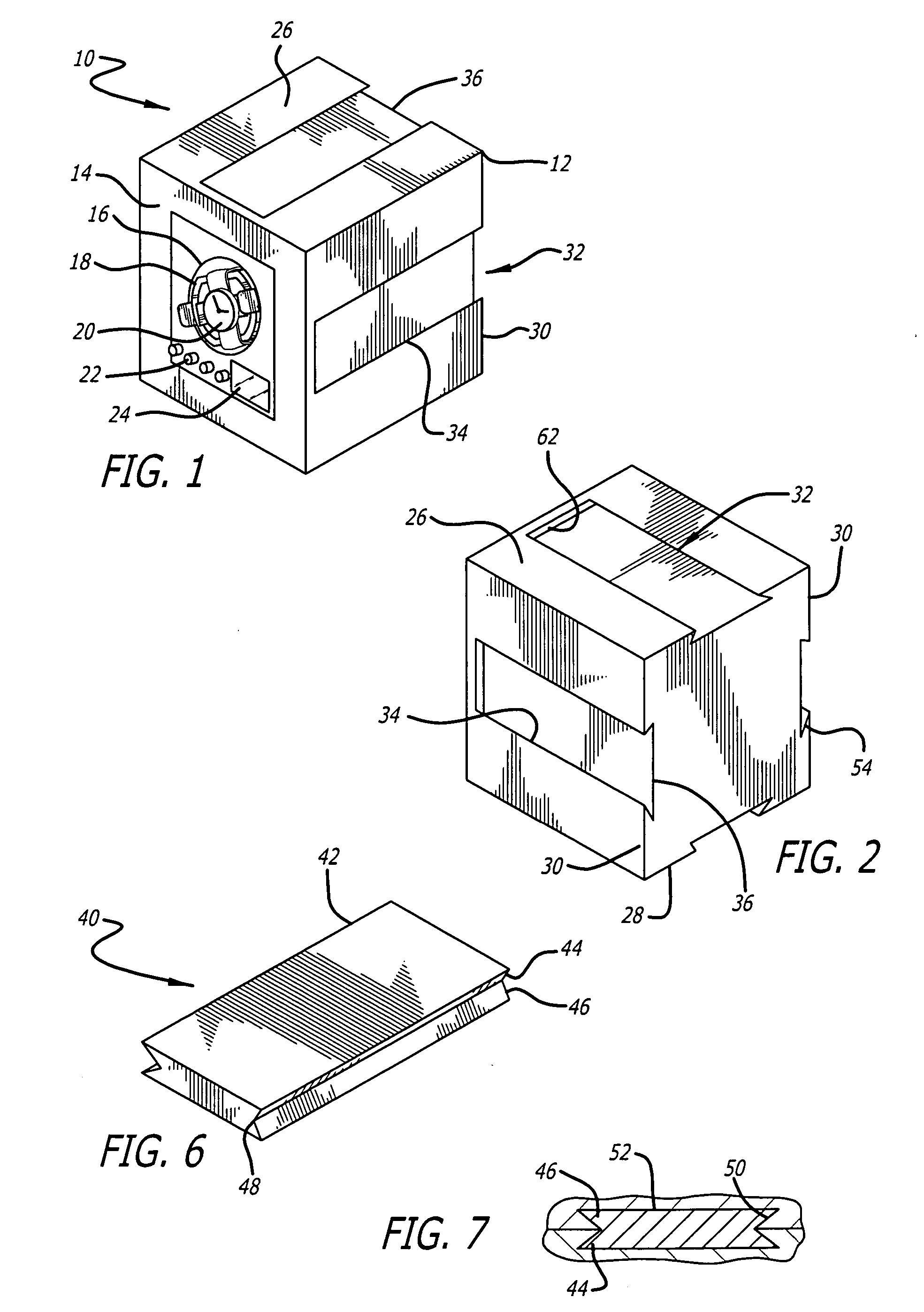
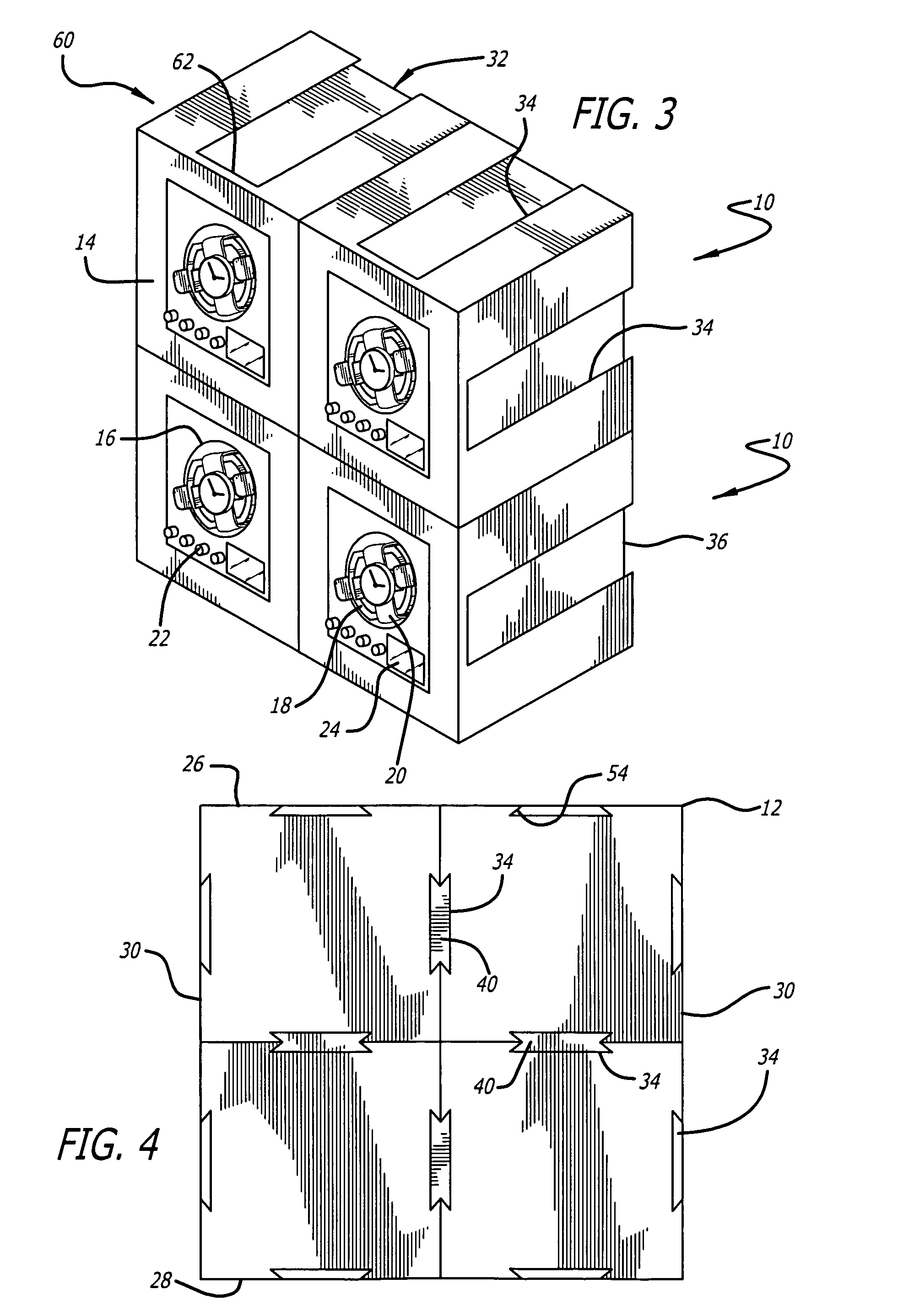
[0026] As shown in the drawings, which are provided for purposes of exemplary illustration, the invention is embodied in a new and improved watchwinder 10, which is capable of being used individually or as part of a customizable and re-configurable grouping of interlocked watchwinders.

[0027] Preferably, as illustrated in FIG. 1 the watchwinder 10 includes a housing 12 of approximately cubic in form, although other shapes or forms of housing also are contemplated by the present invention. The front surface 14 of the housing 12 has an opening therein for receiving a watchwinder mechanism of conventional design. While one or more watchwinder mechanisms could be mounted in a single housing, one mechanism per housing is preferred for the present invention.

[0028] The watchwinder mechanism includes a circular, hollow drum 16, adapted to rotate on its axis, mounted within the housing 12, preferably on an upright generally vertical surface, although it is also contemplated that the front f...


PUM


Abstract

A watchwinder adapted for home use or in a retail store environment includes a horizontal dovetail groove or channel on the top, bottom and side surfaces of the watchwinder housing which cooperates with a removable interlocking bar or rail of mating dovetail shape to selectively and detachably interconnect adjacent watchwinders arranged in a vertical or side-by-side relation. The grooves preferably extend across the horizontal dimension of the watchwinder to a point short of the front of the housing for concealment purposes, and are made relatively wide in relation to the dimensions of the housing to improve rigidity of an interlocked grouping of watchwinders and to simplify assembly. Preferably, the channels are of equal size and shape and spaced equidistantly apart. An array of interlocked watchwinders can be built up to varying size and shape, and one or more of the watchwinders can be selectively removed from anywhere within the array without disturbing the others.

Description

FIELD OF THE INVENTION [0001] This invention relates generally to watchwinders, and more particularly, to a universal watchwinder which can be used individually or as part of a re-configurable and customizable grouping of interconnected watchwinders. BACKGROUND OF THE INVENTION [0002] Self-winding watches have been available for many years and are known to have mechanisms for keeping the watch wound while it is being worn by a user. The automatic winding mechanism of a self-winding watch typically includes a rotary pendulum or similar mechanism that is connected through gears to the mainspring which drives the watch. When the watch is worn, the random movements of the wearer cause the pendulum to oscillate back and forth, or to spin completely about its axis, thereby winding the mainspring of the watch movement. When completely wound, the mainspring will generally have sufficient energy to run to the watch for up to 12 to 48 hours, depending on the particular type of watch. [0003] H...

Claims


Application Information

Patent Timeline
IPC IPC(8): G04B3/00
CPCG04D7/009G04B5/00
Inventor HILL, PAUL D.
Owner WOLF 1834
Why Eureka
Try Eureka