Screw

a screw and head technology, applied in the direction of screws, threaded fasteners, fastening means, etc., can solve the problems of screw rusting easily, difficult to closely touch the object on the bottom surface, and many defects of conventional screws, so as to achieve waterproof effect, high friction resistance, and maintain clean appearance

Inactive Publication Date: 2007-09-27
HSIEH JUI TSE +1
View PDF13 Cites 20 Cited by
  • Summary
  • Abstract
  • Description
  • Claims
  • Application Information

AI Technical Summary

Benefits of technology

[0009] The present invention relates to a screw that comprises an enlarged head and a threaded shank longitudinally extending from said head; said head has an upper surface and an opposite bottom surface with a plurality of ribs protruded therefrom so as to provide with high frictional resistance and waterproof effect when screwing in. Further, the ratio of the outer diameter of said head to the outer diameter of said shank is 1:3.5˜5.5. Accordingly the head has more areas to cover the ejected debris of object for maintaining clean appearance.

Problems solved by technology

In use, the conventional screw has several defects.
Due to the ejected debris, the bottom surface is difficult to closely contact with the object which result of seeping of the water.
Consequently, the screw tends to become rusty easily.

Method used


Image

  • Screw
  • Screw
  • Screw

Examples


second embodiment

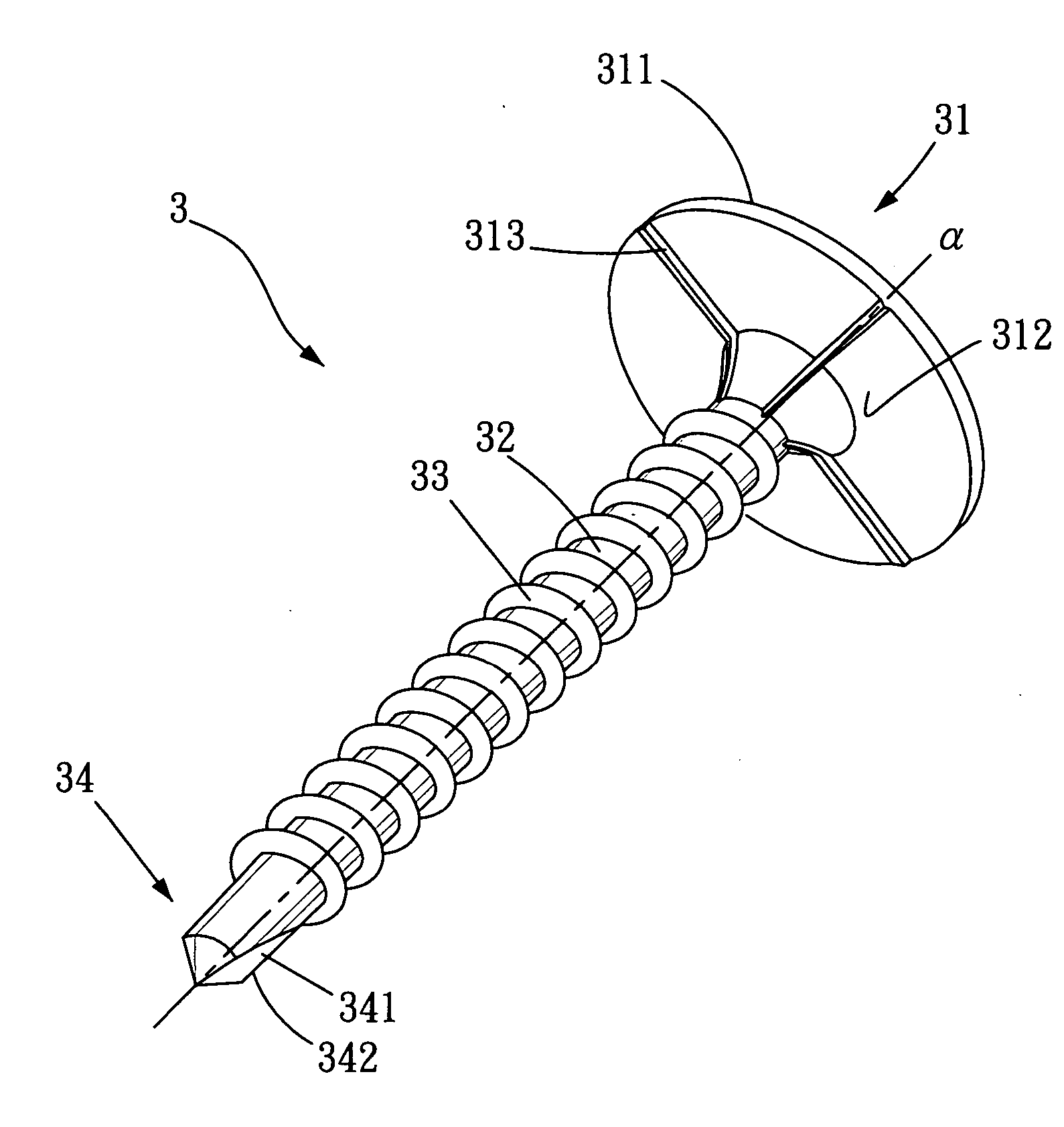
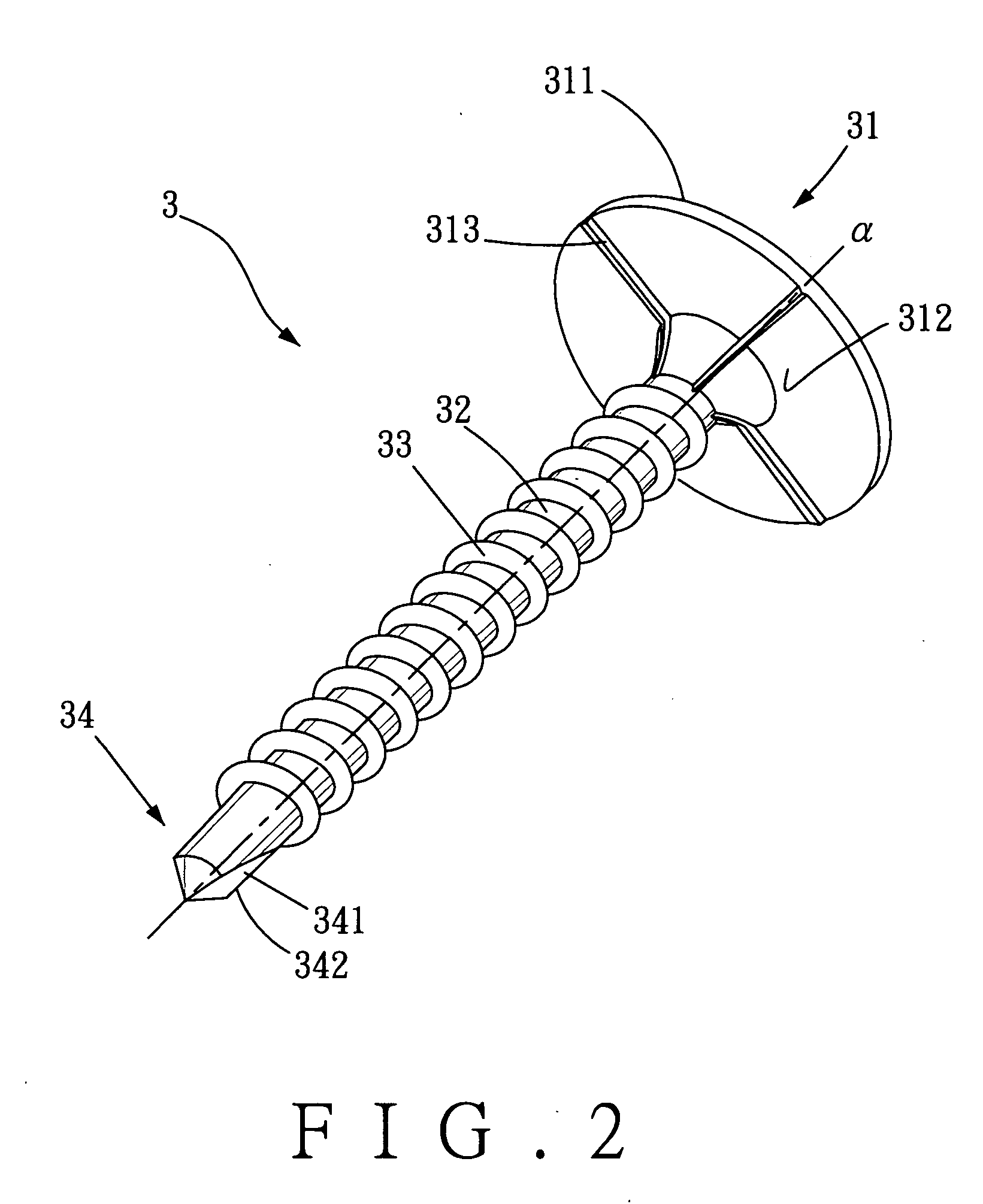
[0019] Referring to FIG. 4, the present invention according to the screw 3, wherein said bottom surface 312 has a cutting ring 314 extending from the outer periphery thereof. Said cutting ring 314 provide with a sharp end. As shown in FIG. 5, during the operation, the cutting ring 314 is able to cut a circumference on the surface of object 4 that is facilitated to merge the head 31 in the object 4 so as to prevent undesired destruction of object 4.

third embodiment

[0020] As illustrated in FIG. 6, the present invention according to the screw 3, wherein said bottom surface 312 has a plurality of annular ribs 315 arranged thereon about the shank axial line α. When screwing, each of said annular ribs 315 firmly engaged with the object 4 so as to block the water to seep in.

[0021] To sum up with above description, the present invention provides the following advantages: [0022] 1. Due to the reason that ratio of the outer diameter of head to the outer diameter of shank is 1:3.5˜5.5 so that the head provided with a board area to cover the debris and thereby the appearance is skillfully and cleanly kept. [0023] 2. By means that a plurality of ribs engaged on the surface of object, the head is able to block the water so as to prevent the screw from becoming rusty. [0024] 3. By means of the cutting ring, said head is able to merge in the object completely so as to avoid the object to be squeezed by the head which result of the destruction of object.

[00...


PUM


Abstract

A screw includes an enlarged head and a threaded shank longitudinally extending from said head; said head has a bottom surface with a plurality of ribs protruded therefrom so as to provide with high frictional resistance and waterproof effect when screwing in. Further, the ratio of the outer diameter of head to the outer diameter of shank is 1:3.5˜5.5. Accordingly the head has greater areas to cover the ejected debris of object so as to maintain clean appearance.

Description

BACKGROUND OF THE INVENTION [0001] 1. Field of the Invention [0002] The present invention relates to a screw with a enlarge head wherein a plurality of ribs is arranged on the undersurface thereof, in particularly to provided with high frictional resistance and waterproof effect. [0003] 2. Description of the Related Art [0004] Referring to FIG. 1, a conventional screw 1 comprises a head 11 and a shank 12 extending therefrom. Said shank 12 has a threaded portion 13 and a drilling portion 14. The drilling portion 14 has two cut grooves 141 disposed thereon. A cutting edge 142 is defined on the boundary of the cut grooves 141 and the outer periphery of the drilling portion 14. In use, said cutting edges 142 cut the object 2 so as to bring the screw in. [0005] In use, the conventional screw has several defects. [0006] 1. Generally, the ratio of the outer diameter of the head to the outer diameter of said shank is 1:2 so that the head has relatively less areas to cover the debris of obje...

Claims


Application Information

Patent Timeline
Patent Type & Authority Applications(United States)
IPC IPC(8): F16B35/06
CPCF16B25/103F16B35/06F16B33/008
Inventor HSIEH, JUI-TSEWANG, CHIU-YUEH
Owner HSIEH JUI TSE
Why Eureka
Try Eureka