Tank mass measurement assembly

a technology for measuring assemblies and tanks, applied in the direction of level indicators, level indicators, instruments, etc., can solve the problems of restricting the modification of tanks storing lpg products, increasing the difficulty of installing a tank mass measuring assembly to the tank, and special problems for the installation of tank mass measuring assemblies

Inactive Publication Date: 2007-10-04
NORTHROP CHARLES L
View PDF9 Cites 5 Cited by
  • Summary
  • Abstract
  • Description
  • Claims
  • Application Information

AI Technical Summary

Problems solved by technology

Storage tanks for hydrocarbon products, a few suitable examples being LPG products such as butane and propane, present special problems for the installation of tank mass measuring assemblies.
Thus, special safeguards are in place, severely restricting the modification of a tank storing LPG products.
The regulations surrounding the modification of a tank storing LPG products drastically increases the difficulty of installing a tank mass measuring assembly to the tank.
Further still, most tanks do not have an appropriate opening or openings able to accommodate the mounting and installation of the mass measuring sensor assembly within the tank.
The welding of the opening is an expensive operation, requiring a certified welder and the shutting down and purging of the tank for the work.
Even if an opening is present on the tank able to accommodate the insertion of the mass measuring sensor assembly within the tank, the tank be must shut down and be purged during the installation procedure, adding great expense to the installation operation.
Further, even if a suitable opening is present on the tank, the opening is virtually never located in the optimum location, i.e., equidistant from the ends of the tank to negate inaccuracies caused by the effects of “slope” when the tank is not oriented perfectly horizontal.
Additionally, due to the complexity of inserting the mass measuring sensor assembly in the tank and the liability associated with modifying the tank, the installation of the tank mass measuring assembly requires highly trained individuals for proper installation further increasing the cost of installation.
However, the mass probe may suffer in accuracy since the mass probe cannot extend in length the full height of the tank since a clearance space must be present at the bottom end of the mass probe to prevent interference between the bottom end of the mass probe and the tank bottom or debris accumulating thereon.
Thus, the accuracy of the mass measuring sensor assembly suffers, especially when the fluid level in the tank is at a very low level.

Method used


Image

  • Tank mass measurement assembly
  • Tank mass measurement assembly
  • Tank mass measurement assembly

Examples


Embodiment Construction

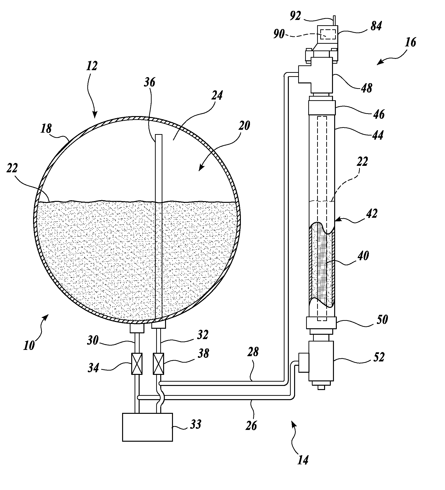
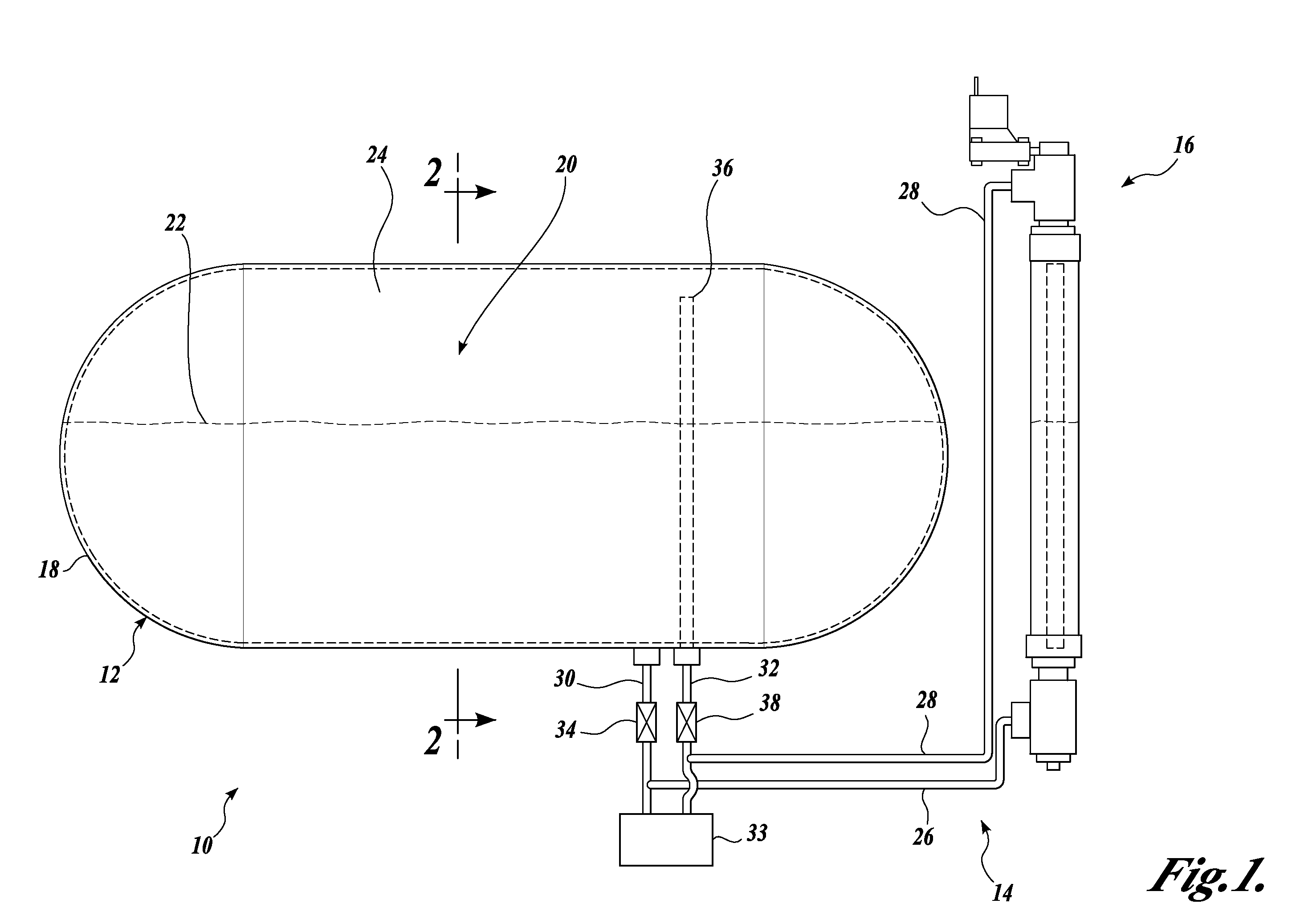
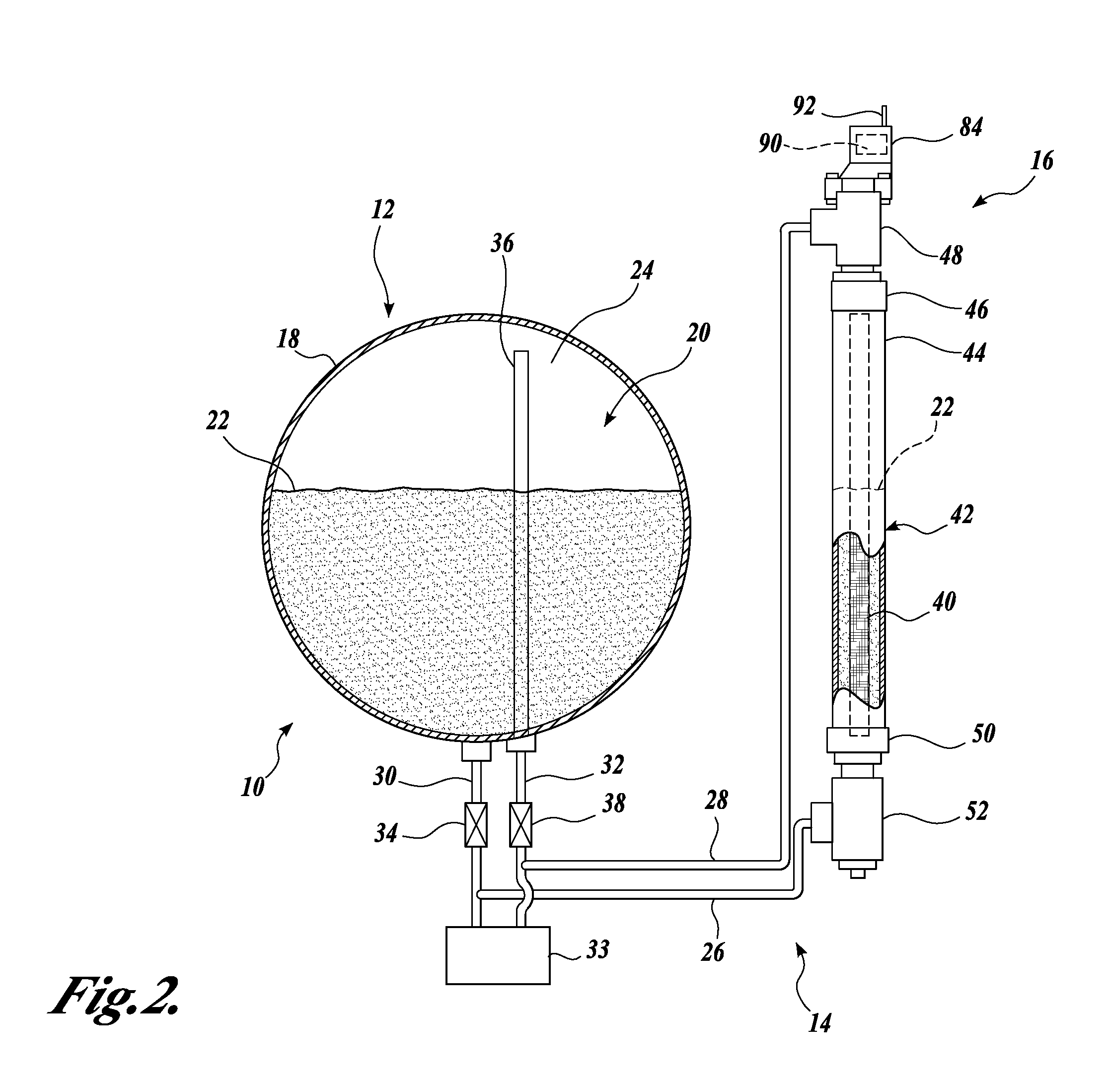
[0018] Turning to FIGS. 1 and 2, one embodiment of a tank mass measuring assembly 10 formed in accordance with the present invention is shown. The tank mass measuring assembly 10 includes a tank 12 for storing a fluid 20, a piping assembly 14, and a sensor assembly 16. The tank 12 of the illustrated embodiment includes a pressure vessel 18 able to store the fluid 20 at an elevated pressure, i.e., a pressure above atmospheric pressure. The tank 12 is preferably adapted for storing a liquefied hydrocarbon product, a few suitable examples being butane and propane, wherein the fluid 20 is stored within the tank 12 as a mixture of a liquid 22 and a vapor or gas 24.

[0019] The piping assembly 14 includes a liquid line 26 and a gas line 28. The liquid line 26 couples the sensor assembly 16 in fluid communication with the tank 12 for permitting the transfer of the liquid 22 between the tank 12 and the remotely located sensor assembly 16. Likewise, the gas line 28 couples the sensor assembly...


PUM


Abstract

A tank mass measuring assembly (10) for monitoring an amount of a fluid (20) stored in a tank (12). The monitoring assembly includes a mass measurement chamber (42) adapted to be located remotely of a tank and adapted to be coupled in fluid communication with the tank to receive a portion of a fluid stored in the tank. The monitoring assembly further includes a sensor assembly (16) at least partially disposed in the mass measurement chamber, the sensor assembly adapted to measure a mass of the fluid disposed in the mass measurement chamber. The sensor assembly is adapted to relay the measured mass to a computation device (90) for determining the amount of the fluid in the tank based upon the measured mass of the fluid disposed in the mass measurement chamber.

Description

CROSS-REFERENCE TO RELATED APPLICATION [0001] This application is a continuation of prior application Ser. No. 11 / 016,390, filed Dec. 16, 2004, priority from the filing date of which is hereby claimed under 35 U.S.C. § 120.FIELD OF THE INVENTION [0002] The present invention relates generally to tank mass measurement assemblies, and more specifically, to tank mass measurement assemblies having a mass measurement chamber located externally of the tank. BACKGROUND OF THE INVENTION [0003] Storage tanks for hydrocarbon products, a few suitable examples being LPG products such as butane and propane, present special problems for the installation of tank mass measuring assemblies. LPG storage tanks are classified as explosion hazards by the National Fire Protection Association (hereinafter “NFPA”), requiring special care in the design and installation of any ancillary equipment. The LPG Code (NFPA 58) defines the area within five feet of any tank, fill opening, or point where liquefied petr...

Claims


Application Information

Patent Timeline
Patent Type & Authority Applications(United States)
IPC IPC(8): G01G9/00
CPCG01F23/0038G01F23/20G01F23/02
Inventor NORTHROP, CHARLES L.
Owner NORTHROP CHARLES L
Why Eureka
Try Eureka