Vacuum valve

a vacuum valve and valve body technology, applied in the field of vacuum valves, can solve the problems of limited closing force that can be applied by these pistons, inability to achieve comparatively large closing force, and relatively uneconomical construction of this vacuum valve on the whole, and achieves simple manner and high closing force

Inactive Publication Date: 2007-10-04
VAT HLDG AG
View PDF12 Cites 32 Cited by
  • Summary
  • Abstract
  • Description
  • Claims
  • Application Information

AI Technical Summary

Benefits of technology

[0008]It is the primary object of the invention to provide a vacuum valve of the type mentioned above which is constructed in a simple manner and in which a high closing force (contact pressing force) can be applied.
[0010]A high closing force can be achieved by means of the driving piston which is arranged in the valve disk and which has a large dimensioning. The closing force is transmitted to the valve housing in a direct path via the tappets. This results in a simple construction and efficient transmission of force.

Problems solved by technology

But the closing force that can be applied by these pistons is limited due to their small dimensions.
However, depending on the differential pressure acting on the valve disk and the size of the valve disk, comparatively large closing forces may be required which cannot be achieved in this construction under certain circumstances.
The construction of this vacuum valve is relatively uneconomical on the whole.
Therefore, the closing force that can be applied is limited, or the carrying arm must be correspondingly massive.
The construction of this valve is uneconomical and the structural height in axial direction of the valve opening is relatively large.

Method used


Image

  • Vacuum valve
  • Vacuum valve
  • Vacuum valve

Examples


Embodiment Construction

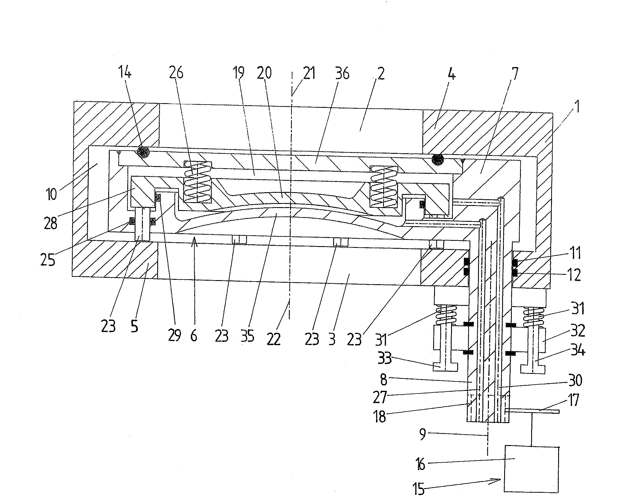
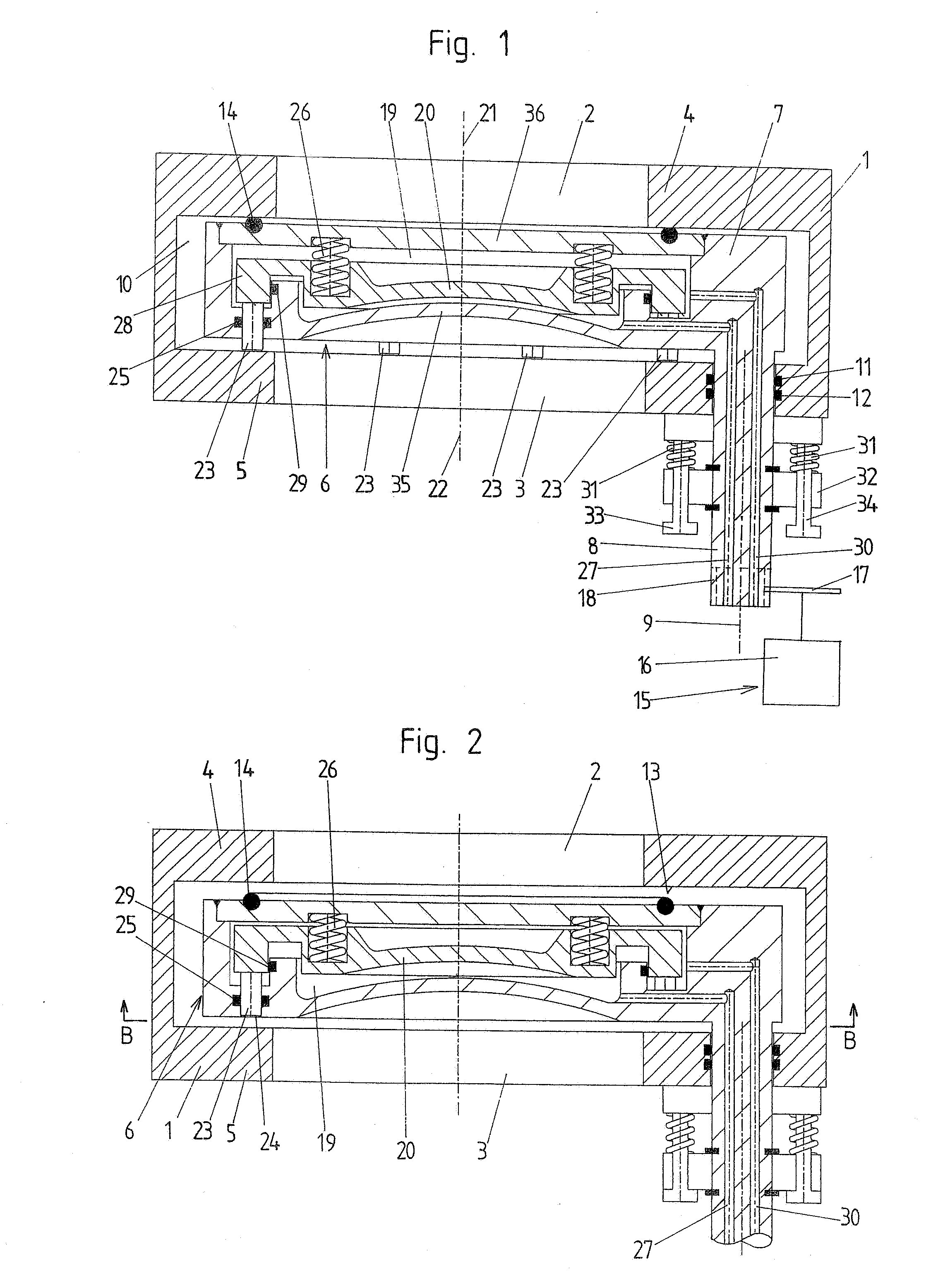
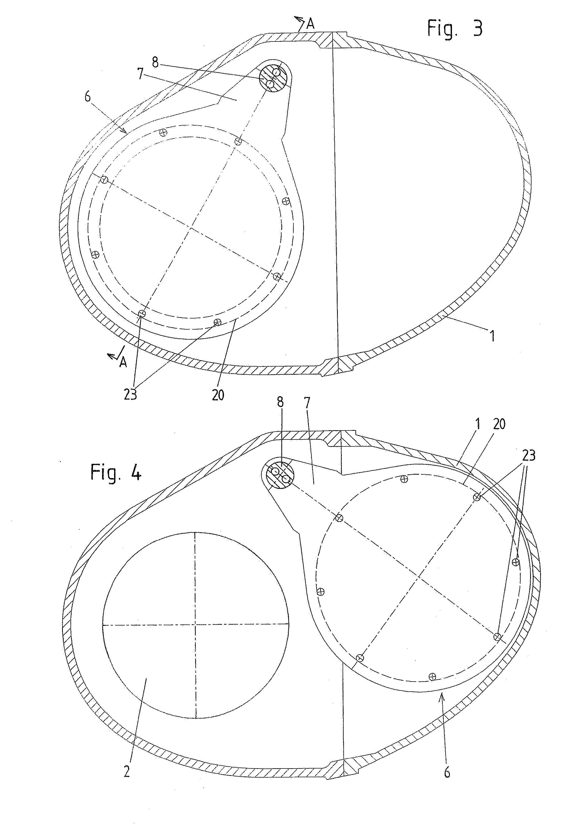
[0021]FIGS. 1 to 4 show a first embodiment form of the invention schematically. The vacuum valve comprises a valve housing 1 which is provided with an inlet opening 2 and an outlet opening 3 which penetrate opposite walls 4, 5 of the valve housing. The center longitudinal axes 21, 22 of the inlet opening 2 and outlet opening 3 lie parallel to one another. In the present embodiment example, the inlet opening 2 and the outlet opening 3 have a circular shape, preferably lie coaxial to one another and have the same diameter.

[0022]A valve disk 6 which is rigidly connected to a swivelable carrying arm 7 is located in the interior space 10 of the valve housing 1. The carrying arm 7 is in turn rigidly connected to a shaft 8 which is mounted so as to be rotatable around its longitudinal axis 9 and displaceable in axial direction. The longitudinal axis 9 of the shaft 8 lies parallel to the center longitudinal axes 21, 22 of the inlet opening 2 and outlet opening 3.

[0023]The shaft 8 is guided ...


PUM


Abstract

A vacuum valve comprises a valve housing which has an inlet opening and an outlet opening, a valve disk which is located in the interior space of the valve housing and which is arranged at a carrying arm that is rigidly connected to a shaft which, for purposes of opening and closing the vacuum valve, is rotatable around its longitudinal axis and displaceable in axial direction, and a driving device for opening and closing the vacuum valve. The driving device comprises a rotary drive for rotating the shaft. The driving device further comprises a driving piston which is arranged in an inner cavity of the valve disk and which has, at least over portions of its circumference, a radial extension which is larger than the outlet opening with respect to the center longitudinal axis of the outlet opening and at which tappets are arranged on the side facing the outlet opening. The tappets are guided out of the inner cavity of the valve disk and are supported in the closed position of the valve disk at the valve housing in the area next to the outlet opening and press the valve disk against the valve seat and can be lifted from the valve housing for displacing the valve disk from its closed position into its intermediate position by means of a displacement of the driving piston. At least one spring element displaces the valve disk into its intermediate position by an axial displacement of the shaft.

Description

CROSS-REFERENCE TO RELATED APPLICATION[0001]This application claims priority of Austrian Application No. A 559 / 2006, filed Mar. 31, 2006, the complete disclosure of which is hereby incorporated by reference.BACKGROUND OF THE INVENTION[0002]a) Field of the Invention[0003]The invention is directed to a vacuum valve comprising a valve housing which has an inlet opening and an outlet opening penetrating opposite walls of the valve housing, a valve seat surrounding the inlet opening, a valve disk which is located in the interior space of the valve housing and is arranged on a carrying arm that is rigidly connected to a shaft which, for purposes of opening and closing the vacuum valve, is rotatable around its longitudinal axis and displaceable in axial direction, and a driving device by which the valve disk can be adjusted from a closed position, in which it is pressed against the valve seat, by way of an intermediate position, in which it is lifted from the valve seat, into an open posit...

Claims


Application Information

Patent Timeline
Patent Type & Authority Applications(United States)
IPC IPC(8): F16K25/00
CPCF16K3/10F16K51/02F16K3/188F16K3/314F16K31/1221
Inventor GEISER, FRIEDRICH
Owner VAT HLDG AG
Why Eureka
Try Eureka