Eureka AIR delivers breakthrough ideas for toughest innovation challenges, trusted by R&D personnel around the world.

Acoustic Decoupling in cMUTs

a technology of cmuts and acoustic energy, applied in the field of cmuts, can solve the problems of high cost, difficult process, and acoustic energy may also leak into the substrate, and achieve the effect of improving acoustic decoupling and minimizing the impact of cmut performan

Active Publication Date: 2007-10-04
KOLO MEDICAL (SUZHOU) CO LTD
View PDF14 Cites 40 Cited by
  • Summary
  • Abstract
  • Description
  • Claims
  • Application Information

AI Technical Summary

Benefits of technology

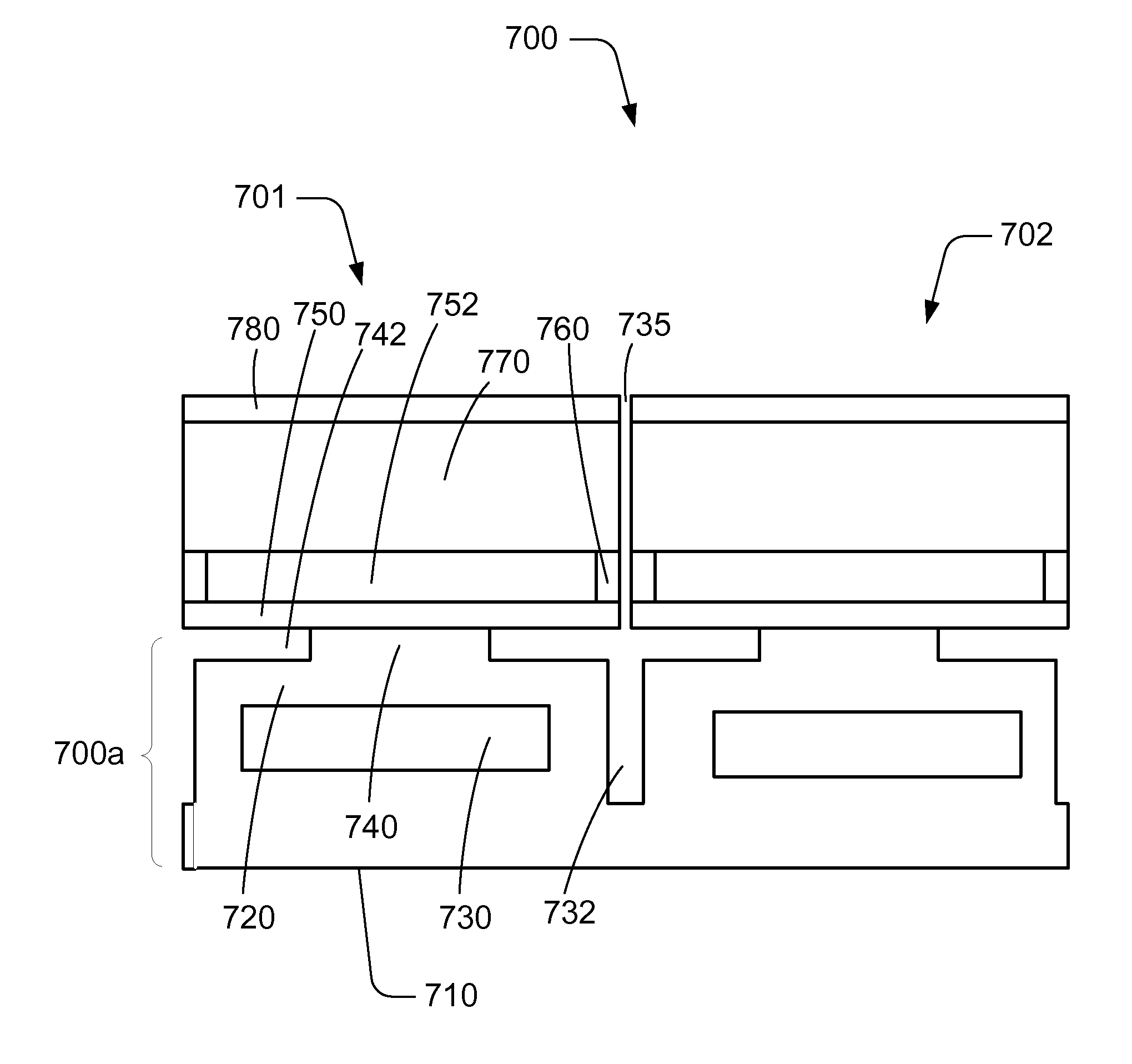
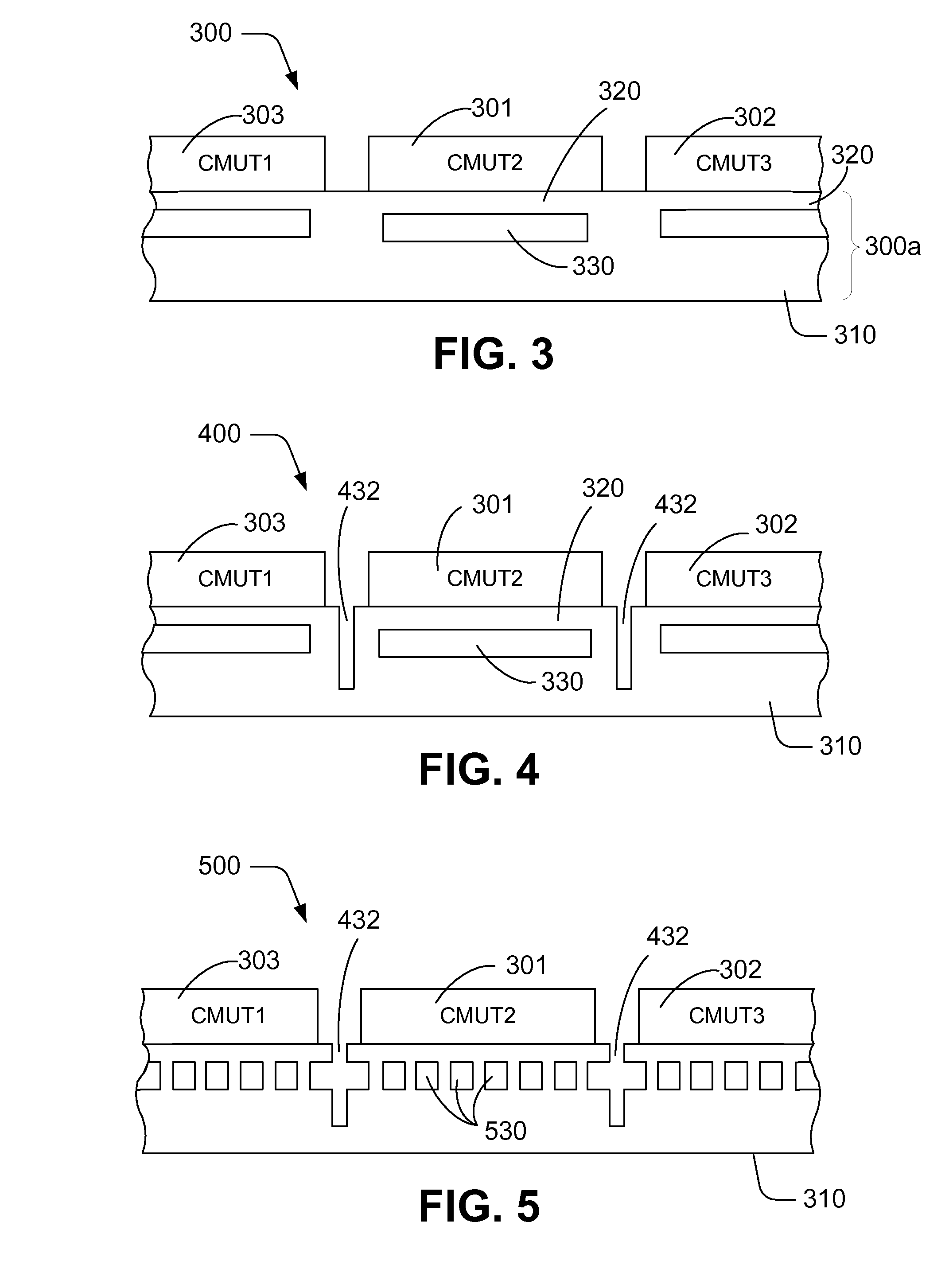
[0012]This application discloses acoustic decoupling features in the substrate to minimize the impact on the cMUT performance by the leaking of acoustic energy in the substrate. A cavity is introduced underneath the regular cMUT element to provide acoustic decoupling. Either a single cavity or multiple smaller cavities may be used for each cMUT element. The cavities may contain a vacuum or filled with a suitable material that is compatible with or has potential to improve acoustic decoupling.
[0013]In some embodiments, trenches are also introduced to separate the cMUT elements and to provide further acoustic decoupling. The trenches may reach deep down into the substrate to reach or even pass the cavity to improve acoustic decoupling performance.

Problems solved by technology

This process is fraught with difficulties and high expenses, not to mention the large input impedance mismatch problem presented by such elements to transmit / receiving electronics.
In addition to emitting into an intended medium, the acoustic energy may also leak into substrate.

Method used


Image

  • Acoustic Decoupling in cMUTs
  • Acoustic Decoupling in cMUTs
  • Acoustic Decoupling in cMUTs

Examples


Embodiment Construction

[0024]The acoustic decoupling feature in cMUT will be described in detail along with the figures, in which like parts are denoted with like reference numerals or letters. The new method may be used with a variety of transducers including capacitive micromachined ultrasonic transducers (MUT).

[0025]This disclosure describes acoustic decoupling features in the cMUT substrate to minimize the impact on the cMUT performance by the leakage of acoustic energy into the substrate. The acoustic decoupling features are introduced to address the issue of leaking acoustic energy in the substrate which may not only affect the performance of each cMUT element but also introduces the cross-talking between cMUT elements.

[0026]FIG. 3 shows a cMUT array having a basic decoupling feature. The cMUT array 300 includes multiple cMUT elements 301, 302 and 303, all built on a cMUT base 300a that includes a lower base portion including the substrate 310, and an upper base portion including layer 320. The deco...


PUM

PropertyMeasurementUnit
Thicknessaaaaaaaaaa
Electrical conductivityaaaaaaaaaa
Electrical conductoraaaaaaaaaa

Abstract

A capacitive micromachined ultrasonic transducer (cMUT) has an acoustic decoupling feature. A cavity is introduced underneath the regular cMUT element, preferably in the substrate, to provide acoustic decoupling. Trenches are also introduced to separate the cMUT elements and to provide further acoustic decoupling. The acoustic decoupling feature may be used in both conventional membrane-based cMUT and the newer embedded-spring cMUT (ESCMUT). Exemplary fabrication methods are also described.

Description

PRIORITY[0001]This application claims priority from U.S. Provisional Application Ser. No. 60 / 744,242, filed Apr. 4, 2006.[0002]This application further incorporates herein by reference in entirety the following:[0003]International Application (PCT) No. PCT / IB2006 / 051567, entitled “METHODS FOR FABRICATING MICRO-ELECTRO-MECHANICAL DEVICES”, filed on May 18, 2006;[0004]International Application (PCT) No. PCT / IB2006 / 051568, entitled “MICRO-ELECTRO-MECHANICAL TRANSDUCERS”, filed on May 18, 2006; and[0005]International Application (PCT) No. PCT / IB2006 / 051569, entitled “MICRO-ELECTRO-MECHANICAL TRANSDUCERS”, filed on May 18, 2006.BACKGROUND OF THE INVENTION[0006]Capacitive micromachined ultrasonic transducers (cMUTs) are electrostatic actuator / transducers, which are widely used in various applications. Ultrasonic transducers can operate in a variety of media including liquids, solids and gas. These transducers are commonly used for medical imaging for diagnostics and therapy, biochemical i...

Claims


Application Information

Patent Timeline
IPC IPC(8): B06B1/06H01L41/00A61B8/00G01H17/00
CPCB06B1/0238Y10T29/49005G01N29/2406B06B1/0292
Inventor HUANG, YONGLI
Owner KOLO MEDICAL (SUZHOU) CO LTD
Why Eureka
Eureka Blog
Learn More