Micro-mechanical modulating element, micro-mechanical modulating element array, image forming apparatus, and method of designing a micro-mechanical modulating element

a micro-mechanical and modulating element technology, applied in the field of micro-electromechanical modulating elements, can solve the problems of substantially uncharted area and difficulty in coping with the case by resorting to a conventional design approach

Inactive Publication Date: 2007-10-04
FUJIFILM CORP
View PDF0 Cites 16 Cited by
  • Summary
  • Abstract
  • Description
  • Claims
  • Application Information

AI Technical Summary

Benefits of technology

[0008] The invention has been devised in view of the above-described consideration, and its object is to analyze the relationship between the size of the movable portion of the micro-electromechanical modulating element of a rotating system and the elastic force of the elastically supporting portion, including the effect of viscosity due to the ambient air, so as to clarify the dynamic behavior of the movable portion, and to realize, on the basis of its knowledge, a structure whereby the movable portion can be appropriately displaced and held at a final displacement position at a low voltage (e.g., 10 V or less).
[0062] According to the invention, it becomes possible to analyze the relationship between the size of the movable portion of the micro-electromechanical modulating element of a rotating system and the elastic force of the elastically supporting portion, including the effect of viscosity due to the ambient air, and clarify the dynamic behavior of the movable portion. On the basis of its knowledge, it becomes possible to reliably and easily realize a structure whereby the movable portion can be appropriately displaced and held at the final displacement position at a low voltage (e.g. 10 V or less).

Problems solved by technology

Under the present situation, knowledge for taking this effect of viscosity into consideration is insufficient, and the precise behavior of the element at a low drive voltage has not yet been fully analyzed, so that it is difficult to cope with the case by resorting to a conventional design approach.
Nevertheless, the dynamic analysis which takes the effect of viscosity into consideration has been such that it can be said to be a substantially uncharted area.

Method used


Image

  • Micro-mechanical modulating element, micro-mechanical modulating element array, image forming apparatus, and method of designing a micro-mechanical modulating element
  • Micro-mechanical modulating element, micro-mechanical modulating element array, image forming apparatus, and method of designing a micro-mechanical modulating element
  • Micro-mechanical modulating element, micro-mechanical modulating element array, image forming apparatus, and method of designing a micro-mechanical modulating element

Examples


first embodiment

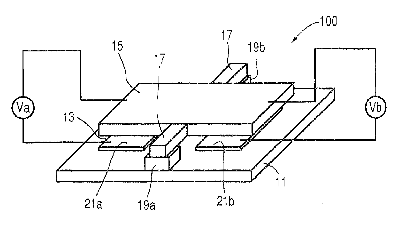
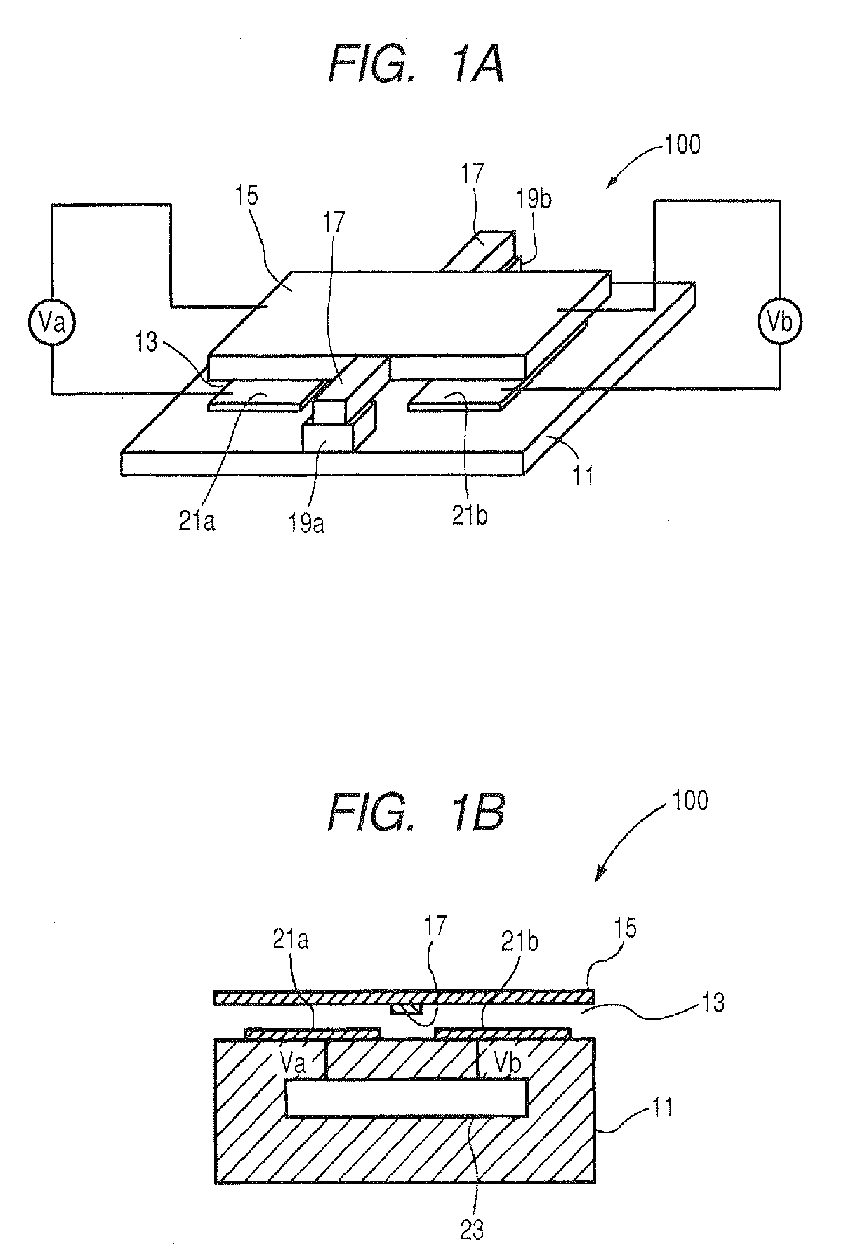
[0118]FIGS. 1A and 1B are conceptual diagrams of the micro-electromechanical modulating element in accordance with the invention, in which FIG. 1A is a perspective view of the micro-electromechanical modulating element, and FIG. 1B is a vertical cross-sectional view thereof.

[0119] A micro-electromechanical modulating element 100 in accordance with this embodiment has as its basic constituent elements a substrate 11; a movable portion 15 in the form of a small piece disposed over the substrate 11 parallel thereto with a gap provided therebetween; a hinge 17 which is an elastically supporting portion connected to the substrate 11-side surface of the movable portion 15 to support the movable portion 15; a pair of spacers 19a and 19b for supporting the movable portion 15 over the substrate 11 by means of this hinge 17; and a first address electrode 21a and a second address electrode 21b which are drive electrodes (fixed electrodes) disposed on both sides with the hinge 17 as a center. ...

second embodiment

[0243] The structure of the micro-electromechanical modulating element is not limited to the one shown in FIG. 1, and may be a different one. FIGS. 25A to 25C respectively show other examples of the configuration of the micro-electromechanical modulating element.

[0244] In the micro-electromechanical modulating element shown in FIG. 25A, the hinge 17 is joined to a quadrangular movable portion 25A such that one diagonal line of the movable portion 25A serves as an axis of the rotational motion. Both end portions of the hinge 17 are respectively supported by the pair of spacers 19a and 19b. By virtue of this configuration, a shorter inertial force in the rotational displacement of the movable portion 25A is required, which is advantageous in high-speed drive.

[0245] The micro-electromechanical modulating element shown in FIG. 25B has a pair of hinges 17A and 17B respectively extending from both ends of a movable portion 15B, as well as the pair of spacers 19a and 19b for supporting t...


PUM

PropertyMeasurementUnit
hold voltageaaaaaaaaaa
voltageaaaaaaaaaa
voltageaaaaaaaaaa

Abstract

A micro-electromechanical modulating element including a plurality of movable portions as defined herein and a plurality of driving portions as defined herein, wherein a dynamic pull-in voltage defined herein is set to be lower than a hold voltage defined herein, and the driving portion drives the movable portion by a drive voltage greater than or equal to the hold voltage and the drive voltage is less than or equal to 10 V.

Description

FIELD OF THE INVENTION [0001] The present invention relates to a micro-electromechanical modulating element (in particular, the structure of a micro-electromechanical modulating element of a rotating system which is driveable at a low voltage and rotates bidirectionally, as well as dynamic analysis and condition setting, including a viscous effect, for driving the modulating element at a low voltage), a micro-electromechanical modulating element array, an image forming apparatus, and a method of designing a micro-electromechanical modulating element. BACKGROUND OF THE INVENTION [0002] In recent years, due to the rapid progress of an MEMS technology (MEMS: Micro-Electromechanical Systems), development of micro-electromechanical modulating elements for electrically displacing and moving a micro-mechanical element of μm order has been actively carried out. Among the micro-electromechanical modulating elements, for example, a digital micromirror device (DMD) manufactured by Texas Instru...

Claims


Application Information

Patent Timeline
Patent Type & Authority Applications(United States)
IPC IPC(8): H01F7/08
CPCG02B26/0841H01F2007/068H02N1/006H01H59/0009H01H47/04
Inventor OGIKUBO, SHINYAKIMURA, KOICHIMOCHIZUKI, FUMIHIKONAKAMURA, HIROCHIKA
Owner FUJIFILM CORP
Why Eureka
Try Eureka